Do you have a question about the Pitney Bowes DI380 Series and is the answer not in the manual?
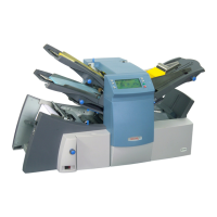
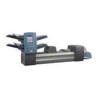
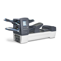
Manual supports installation and site repair of the DI380/DI425/SI3300/SI3500 Inserter.
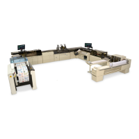
Manual applies to sheet feeder, accessories, and interface kits for tabletop system operation.
Explains warning, caution, and important messages for safe operation and potential hazards.
Guidelines to protect sensitive equipment from static damage and general safety precautions.
Details sheet feeder, insert feeder, paper weights, fold configurations, and thickness limits.
Provides physical dimensions, noise level, electrical requirements, and maximum speed for models.
Explains the low volume, easy-to-use nature of the Folding/Inserting machines.
Describes the process of feeding a single sheet with an envelope and collation.
Details the process of feeding a single insert with an envelope and collation.
Explains the function and positions of double detection sensors.
Steps for removing machine covers and the logic board.
Steps to remove the sheet feeder separator roller and pad assembly.
Detailed steps for dismantling the DI380 insert feeder.
Instructions for removing the envelope feeder for DI425/SI3500.
Steps to remove the power supply unit and AC motor.
Adjusts side guides to the middle of the tray for proper feed.
Enables envelope to feed biased left or right for better insertion.
Adjusts flipper height and hold down solenoid for proper operation.
Sets offset values for fold plates to match job setup dimensions.
Covers alignment, calibration, and height adjustments for the Q station.
Explains OMR sensor placement, adjustability, and paper size support.
Details mark requirements, paper weight, width, and clear zone specifications.
Illustrates standard OMR mark placement for different fold types.
Explains OMR code structure, groups, and data marks for different folds.
Steps to enable Basic OMR and Enhanced OMR options.
Steps to access the service menu and navigate its options.
Allows engineers to change NVM settings, including machine configuration.
Guides for testing components using the control panel.
Detailed charts correlating error codes with operator checks and diagnostics.
Overview of service intervals and items to check, clean, or replace.
Checklist for 100,000 cycle preventive maintenance.
Checklist for 200,000 cycle preventive maintenance.
Steps for unpacking the machine, checking for damage, and initial setup.
Guide for training operators on machine layout, functions, and operation.
Visual representation of machine operation for DI380/SI3300 and DI425/SI3500.
Diagrams showing the location of various components on the PCBs.
Tables detailing test levels for mechanical switches, barrier switches, and sensors.
Schematic showing wiring for insertion, moistener, and exit areas.
Schematic for the display and power supply unit connections.
| Double Document Detection | Yes |
|---|---|
| Weight | 385 lbs |
| Envelope Capacity | 325 envelopes |
| Fold Types | C-fold, Z-fold, half-fold |
| Optical Mark Recognition (OMR) | Optional |
| Barcode Recognition | Optional |
| Output Stacker Capacity | 500 |
| Connectivity | Ethernet, USB |
| Document Size | 5" x 7" to 14" x 9" |
| Document Sizes | 5" x 7" to 14" x 9" |