PDRP-1001/PDRP-1001A Document 50734 Rev B 12/21/97
8
LED Interface Module (4XLM NOTIFIER)
Maximum voltage/current, each output: 27.6V/8mA.
Note: Outputs are power limited.
Zone Relay Module (4XZM NOTIFIER)
Dry Form-C contacts rated: 2.0 amps @ 30 VDC (resistive), 0.5 amps @ 30 VAC (resistive).
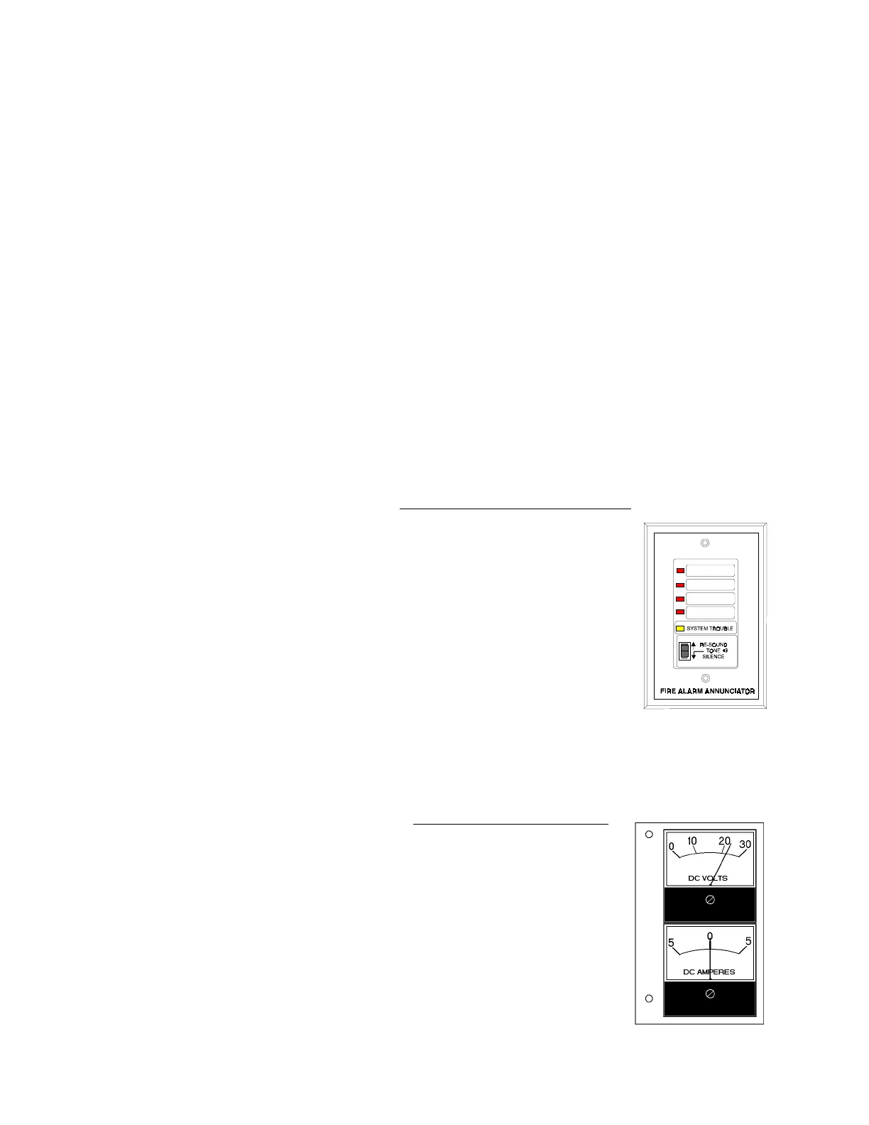
1.4 Remote Annunciator
Remote Annunciator (RZA-4X NOTIFIER)
The Remote Annunciator mounts on a standard single-gang box, and provides LED
indication of the following:
• Alarm/Waterflow Bell (red)
• Waterflow/Supervisory Bell (red)
• Releasing Circuit 1 (red)
• Supervisory Bell/Release Circuit 2 (red)
• System Trouble LED (yellow)
A Local Trouble Sounder and Silence Switch are also provided. All LED wiring is
supervised for open conditions. Any open condition will cause the System Trouble
LED to illuminate.
Note: The Remote Annunciator requires the use of an LED Interface module (4XLM).
1.5 Optional Meters
Voltage, Current Meters (4XMM NOTIFIER)
The Meter Module provides a voltmeter to measure the voltage across the
batteries and an ammeter to measure the charging current to the batteries. The
meters are provided as a assembly that mounts to the lower left corner of the
cabinet.
Transmitter Module (4XTM NOTIFIER)
For Local Energy Municipal Box service (NFPA 72 Auxiliary Fire Alarm System)
Supervisory current: 5.0 mA.
Trip current: 0.35 amps (subtracted from Notification Appliance power).
Coil Voltage: 3.65 VDC.
Coil resistance: 14.6 ohms.
Maximum allowable wire resistance between panel and trip coil: 3 ohms.
Municipal Box wiring can leave the building.
For Remote Station service (NFPA 72 Remote Station Fire Alarm System):
Maximum load for each circuit: 10 mA.
Reverse polarity output voltage: 24 VDC.
Remote Alarm and Remote Trouble wiring can leave the building.