10/24
5.4 Replacement of the actuator
Attention:The machine manufacturer must restrict access to the sensor
programming mode to authorised personnel only.
Via input I3 it is always possible to replace the coded actuator with a second actuator
at any time. By activating this input the device sets to the programming mode and the
IN LED flashes orange; it disables all OS1, OS2, O3, O4 outputs and releases the
actuator. With the input enabled, insert the second actuator. Acquisition of the second
actuator is confirmed by the IN LED switching off and by four flashes of the ACT LED.
At this point the I3 input can be disabled. The device will automatically set to restart
and the first actuator will no longer be recognised.
The second actuator must be suitably fixed to the guard as described in paragraph
INSTALLATION INSTRUCTIONS.
This operation must not be carried out as a repair or maintenance operation. If
the device ceases to function correctly, replace the entire device and not just the
actuator.
5.5 Reset input
The following error states due to a failure external to the device can be rest using the
I3 input:
- a short circuit or overcharge of safety outputs (OS1, OS2),
- a short circuit between a safety output and the supply voltage,
- an excessive misalignment between the device and the locked actuator.
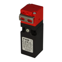
5.6 Connection in series with safety modules
It is possible to install multiple cascade-connected devices, up to a maximum of 32
units, whilst maintaining safety category 4 / PL e according to EN ISO 13849-1 and
integrity level SIL CL 3 according to EN 62061.
Check that the PFH
d
value and MTTF
d
value of the system consisting of the cascade
of devices and the entire safety circuit meet the requirements of the SIL/PL level
requested by the application.
Application example with single channel
locking control function
Application example with dual channel
locking control function
NG
NG
NG
CS
CS AM
CS FS
OS1 OS2
IS1 IS2
IS1 IS2
OS1 OS2
IS1 IS2
OS1 OS2
Ixx Ixx Ox
I4
VN NG-F3•
VN NG-F3•
VN NG-F3•
+ Vcc
I4
I4
NG
NG
NG
OS1 OS2
IS1 IS2
IS1 IS2
OS1 OS2
IS1 IS2
OS1 OS2
OS1 OS2
VN NG-F3•
VN NG-F3•
VN NG-F3•
+ Vcc
CS MP
Ixx Ixx
IE1
IE2
IE1
IE2
IE1
IE2
Device with mode 1
Lock detection function (guard locked): 2
channels / Category 4 / up to SIL 3 / PL e
Locking control function:
1 channel / Category 2 / up to SIL 2 / PL d
Device with mode 1
Lock detection function (guard locked): 2
channels / Category 4 / up to SIL 3 / PL e
Locking control function:
2 channels / Category 4 / up to SIL 3 / PL e
Device with mode 2
Interlock detection function (guard closed): 2
channels / Category 4 / up to SIL 3 / PL e
Locking control function:
1 channel / Category 2 / up to SIL 2 / PL d
Device with mode 2
Interlock detection function (guard closed): 2
channels / Category 4 / up to SIL 3 / PL e
Locking control function:
2 channels / Category 4 / up to SIL 3 / PL e
When connecting the devices in series as described above, observe the following:
- Connect the inputs of the first device in the chain to the supply voltage.
- The OS1 and OS2 safety outputs of the last device in the chain must be connected
to the safety circuit of the machine.
- Where a safety module is used, check that the properties of safety outputs OS1/
OS2 are compatible with the safety module inputs (see paragraph INTERFACING).
- Respect the stray capacitance limits on the output lines indicated in the electrical
data (see paragraph TECHNICAL DATA).
- Check that the response time of the cascade meets the requirements of the safety
function to be implemented.
- The activation time of the cascade must be calculated taking into account the re-
sponse time of every single device.
5.7 Operating states
PWR
LED
IN
LED
OUT
LED
ACT
LED
LOCK
LED
EDM
a
Device
state
Description
O O O O O O OFF Device switched off.
green
/ red,
alter-
nating
green
/ red,
alter-
nating
green
/ red,
alter-
nating
green
/ red,
alter-
nating
green
/ red,
alter-
nating
green
/ red,
alter-
nating
POWER
ON
Internal tests upon activation.
green O O
green RUN Safety inputs of the device not
active.
green green
RUN Activation of safety inputs.
green green /
orange,
alterna-
ting
O
RUN Safety inputs incoherence.
Recommended action: check
for presence and/or wiring of
inputs.
green
blinking
red
RUN Incoherence of solenoid acti-
vation inputs IE1, IE2.
Recommended action: check
for presence and/or wiring of
inputs.
green
green RUN Actuator in safe area. O3 si-
gnalling output active.
green
green green O RUN Actuator in safe area and
locked; O3 and O4 outputs
active.
green green green green green O RUN Mode 1
Activation of safety inputs IS1,
IS2. Actuator in safe area and
locked. O3, O4, OS1 and OS2
outputs active.
green green green green O RUN Mode 2
Activation of safety inputs IS1,
IS2. Actuator in safe area. O3,
OS1 and OS2 outputs active.
green orange orange green green O RUN Mode 3.
Actuator present, guard clo-
sed and locked, IS1 enabled,
IS2 disabled, OS1 enabled,
OS2 disabled
green green orange green O O RUN Mode 3.
Actuator present, guard clo-
sed and not locked, IS1 and
IS2 enabled, OS1 disabled,
OS2 enabled
green
red,
alterna-
ting
ERROR Error on safety outputs. Re-
commended action: check for
any short circuits between the
outputs, outputs and ground
or outputs and power supply,
then restart the device.
green O O red,
alterna-
ting
O O ERROR Actuator detection error.
Check the physical integrity of
the device and, in case of fai-
lure, please replace the entire
device. If undamaged, realign
the actuator with the device
and restart the device.
red O O O O O ERROR Internal error. Recommended
action: restart the device. If
the failure persists, replace
the device.
red,
alterna-
ting
O O O O O ERROR Temperature error outside the
permissible range
green
O green RUN EDM signal active (external
relay off)
a
green green green green green O RUN EDM signal not active
(external relay on)
a
green O O O O red,
alterna-
ting
ERROR Error in the EDM
a
function
O = off = indifferent (a) = available only in version NG 2•••5•••
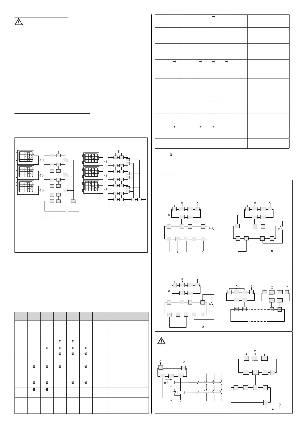
5.8 Interfacing
Connections with CS AR-08•••• safety
modules
Input configuration with monitored start
Connections with CS AR-05•••• / CS
AR-06•••• safety modules
Input configuration with manual start (CS
AR-05••••) or monitored start (CS AR-06••••)
S33
S21 S22
S35
S34
A2
S52
S12
A1
-
+
OS2
OS1
IS2
IS1
A1
+
A2
-
NG
CS
S21 S22
S34
A2
A1
-
+
S52
S12
OS2
OS1
IS2
IS1
A1
+
A2
-
NG
CS
Connections with CS AT-0••••• / CS
AT-1••••• safety modules
Input configuration with monitored start
Connections with CS MF••••0, CS
MP••••0 safety modules
The connections vary according to the program
of the module
S33
S21 S22
S35
S34
A2
A1
-
+
S31
S12
OS2
OS1
IS2
IS1
A1
+
A2
-
NG
CS
OS2
OS1
IS2
IS1
A1
+
OS2
OS1
IS2
IS1
A1
+
A2
-
A2
-
NG
NG
CS
EDM connection
Caution: if all OS safety outputs are
connected directly to a safety contactor,
we recommend using fast switching diodes
connected in parallel to the contactor coils.
OS2
OS1
I5
A1
+
A2
-
NG 2•••5•••
KM1
KM2
Connections with expansion module CS
ME-03••••
For NG 2•••5••• devices only
with mode 1 or 2
OS2
OS1
IS2
IS1
A1
+
A2
-
NG
I5
OS2
OS1
EDM EDM
A2
CS
 Loading...