20
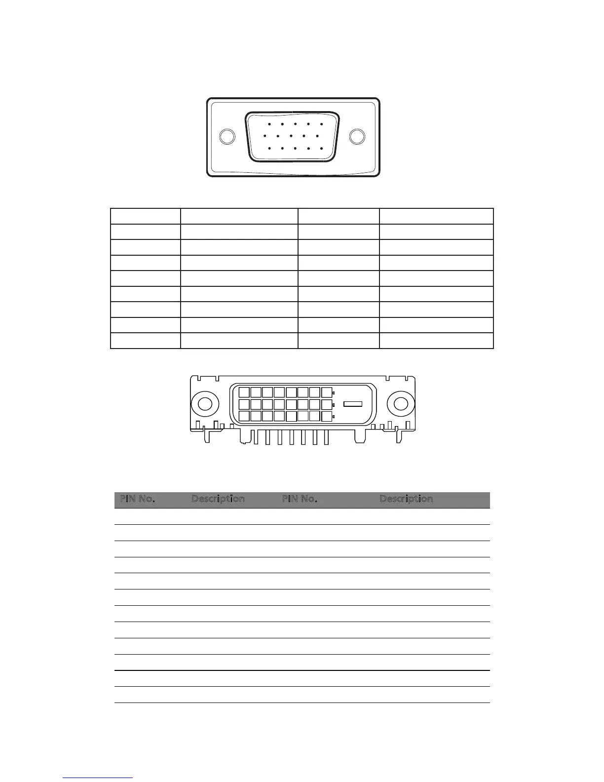
CONNECTOR PIN ASSIGNMENT
1 5
6
10
11 15
15 - Pin Color Display Signal Cable
PIN NO. DESCRIPTION PIN NO. DESCRIPTION
1. Red 9. +5V
2. Green 10. Detect Cable
3. Blue 11. Ground
4. Ground 12. DDC-Serial Data
5. Ground 13. H-Sync
6. R-Ground 14. V-Sync
7. G-Ground 15. DDC-Serial Clock
8. B-Ground
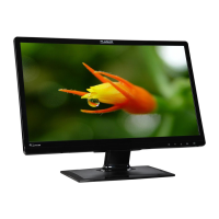
24-pin color display signal cable*
PIN No. Description PIN No. Description
1 TMDS data 2- 13 NC
2 TMDS data 2+ 14 +5 V power
3 TMDS data 2/4 shield 15 GND (return for +5 V hsync.vsync)
4 NC 16 Hot-plug detection
5 NC 17 TMDS data 0-
6 DDC clock 18 TMDS data 0+
7 DDC data 19 TMDS data 0/5 shield
8 NC 20 NC
9 TMDS data 1- 21 NC
10 TMDS data 1+ 22 TMDS clock shield
11 TMDS data 1/3 shield 23 TMDS clock+
12 NC 24 DDC TMDS clock-
E N-6
* only for certain models