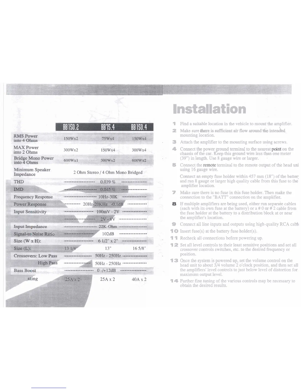
Installation
Wind
a
suit;~b.le
Iocatiozn
in
the ~ebicle to mount
the
mp1ifier.
P
~s~e
sun
is nacien[
air
flow
mund-e
inten&,
mounting location.
3
Att3sch
the
amplifier to
the
mounting surface using
wrews.
4
Connect
tb
power
ground
termbad
to
the
nearest
mm
the
cfras~is
af
tht:
ear.
Keep
this
gourd
wire
less
than
me
meter
(38"3
in
l@n@h.
Use
8
gauge
wire
m
larger.
.
85
Comtxt the
terminal to the remote
oupt
of
thk head u&
using
16
gauge
wire.
Cmect
m
empty
fuse
holder within
457
~un
(18")
of-the
barn
an$
run
8
gauge or larger high quality cable from
this
fuse
to tk
amplifier
1~cation.
Y
Make sure
there
is
no fuse
tin
this
fuse
hick.
Then
m&
the
connectian to the
"BATT"
comectim
on
the
amplifir.
If
mlrtltiple mplifiw$
are
being
uwd,
either
run
sep& cables
(each with
it$ own
fuse
at
the
battery)
or a
9
0
tx
#
2
cable
fmm
the
fuse
balder
at
the
battery
to
a
distribution block
at
~r
mar
the
mplifier's location.
S
Connect
dl
line inputs and outputs using high-quality
RCA
cab%
"1
Insert fusets) at the battery fuse holder(s).
I
1
Recheck all connections before powering
up.
I
Ih
Set
all
level controls
to
their bast sensitive pitions
and
set a11
crossover controls switck, etc. to
the
desired
fbxpmcy
or
position.
1
3
Once the system is powered up, set
the
volume control on the
head unit
to
abut
3/4
volume
2
o'clock position, and then set
all
the amplifiers' level controls to just below level of distortion for
maximum output level.
1
Fuse
R
A
I
4
Further
fine
tuning of the various controls may
be
necessary to
obtain the desired results.
 Loading...