Aircraft Alternator
Maintenance Manual
24-30-01 ES1031
Page: 6-2 Rev. A: 11 Aug. 2021
© 2021 - Hartzell Engine Technologies - All rights reserved
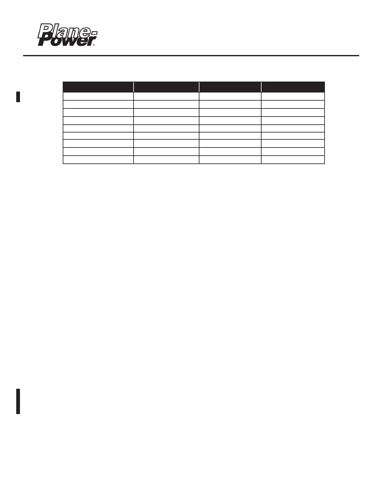
6.3 Torque Information
* Use a 5/16 inch hex key to hold shaft while applying torque to output shaft nut.
** Attachment of Ground, Battery, Aux. or Field wires from the engine or airframe may use above torque unless
Always hold the bottom nut when applying torque to top nut to prevent over torque of bottom nut.
*** The engine/airframe OEM or the supplier of the drive coupling or belt drive may indicate a torque value for
airframe OEM torque value shall supersede the HET value above.
6.4 Alternator Drive Coupling Inspection & Maintenance
(ES-10024, ALV-9610, & ES-6024D)
A. Although the alternator drive coupling is provided by the engine or airframe manufacturer who have issued
manuals and/or instructions regarding their maintenance, the coupling is fundamental to the operation of
Hartzell Engine Technologies LLC (HET) alternator. As such, some general troubleshooting regarding
Troubleshooting section 3.
(1) Check for any and all service information from the engine, airframe and the drive coupling
manufacturer concerning the installation, inspection, and replacement of the drive coupling.
(2) Check the general condition of the drive coupling (requires removal of the alternator).
(3) Check the shaft nut and cotter pin for damage (damage to these parts will indicate interference with
internal engine parts). If damaged, determine cause.
(4) Using the manufacturer’s service information, check the condition of the gear teeth and the elastomer
insert. If damaged, replace or overhaul the drive coupling.
(5) Whenever the alternator is overhauled, HET recommends that the drive coupling be replaced. If
the alternator cannot be overhauled or repaired and is being replaced, the coupling should also be
replaced.
(6) To further aid inspection, Continental Motors includes drive coupling service information in the
appropriate engine manuals and also in service bulletins. (Refer to the latest CMI SB11-3 and/or SB95-
3B for drive coupling service information.)
Reference Description Torque Value (US) Torque Value (SI)
Figure 6.1 (gear) Output Shaft Nut 25-37.5 ft-lbs*** 33.9-50.8 Nm
Figure 6.2 (belt) Output Shaft Nut* 55-65 ft-lbs*** 74.6-88.1 Nm
Section 2.7 Through Bolts 45-50 in-lbs 5.08-5.65 Nm
Section 2.7 (top & bottom) Ground Nut (NEG)** 25-30 in-lbs 2.82-3.39 Nm
Section 2.7 (top & bottom) Output Nut (POS)** 70-85 in-lbs 7.91-9.60 Nm
Figure 6.4 Screws (Brush Holder) 11-14 in-lbs 1.24-1.58 Nm
Section 2.7 (top & bottom) AUX Nut 25-30 in-lbs 2.82-3.39 Nm
Figure 6.4 (bottom only) Field Nut (F1 & F2) 12-15 in-lbs 1.36-1.69 Nm
Figure 6.4 (top only) Field Nut (F1 & F2) 6-8 in-lbs 0.68-0.90 Nm
Table 6.1 - Torque Specifications
 Loading...