- 1 -
- 2 -
- 3 -
- 4 -
- 5 -
- 6 -
- 7 -
- 8 -
Logging in to the Industrial Modbus Gateway
1. Use Internet Explorer 8.0 or above Web browser and
enter IP address http://192.168.0.100 to access the
Web interface.
2. When the following dialog box appears, please enter
the default user name and password “admin”. The
login screen in Figure 4-2 appears.
Default Username: admin
Default Password: admin
Figure 4-2: Web Login Screen
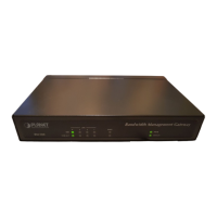
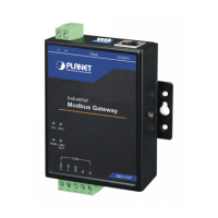
1. Package Contents
Thank you for purchasing PLANET Industrial 1-port/2-
port RS422/485 Modbus Gateway, IMG-110T/120T.
“Industrial Modbus Gateway” mentioned in this
quick installation guide refers to the IMG-110T/120T.
Open the box of the Industrial Modbus Gateway and
carefully unpack it. The box should contain the following
items:
Industrial Modbus
Gateway x 1
Quick Installation
Guide x 1
User’s Manual
CD x 1
If any item is found missing or damaged, please contact
your local reseller for replacement.
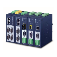
3. Physical Introduction
1
RS422/485 Serial
IMG-110T:
5-contact terminal
block connector
IMG-120T:
10-contact terminal
block connector
6
9 8 7
5
4
3
2
1
RS422/485
Terminal block
1 2 3 4
ON
ECE
10/100TXResetV+
LNK/
ACT
PWR
RX1TX1
RX2TX2
IMG-120T
COM1
T+/D+
GND
R+
COM2
T+/D+
GND
R+
Industrial
Modbus Gateway
2
Ethernet port LED
indicator (LNK/ACT)
3 Power LED indicator
4
Serial receive data
indicator (RX)
5
Serial transmit data
indicator (TX)
6 Wall mounting Kits
7
10BASE-T/
100BASE-TX
8
Reset DIP switch
(Please refer to
Chapter 5 for detail)
9
Power input
9~48VDC
PIN RS485 PIN Dene RS422 PIN Dene
1 D+ T+
2 D- T-
3 GND GND
4 -- R+
5 -- R-
IMG-120T: The 10-contact terminal block connector
on the lower panel of the Industrial Modbus Gateway is
used for RS422/485 connection.
1 2 3 4 5 6 7 8 9 10
Serial port PIN RS485 PIN dene RS422 PIN dene
COM1
1
D+ T+
2
D- T-
3
GND GND
4
-- R+
5
-- R-
COM2
6
D+ T+
7
D- T-
8
GND GND
9
-- R+
10
-- R-
2. Requirements
z Ethernet Port Connection
z Workstations running Windows XP/2003/Vista/7/8/
2008/10, MAC OS X or later, Linux, UNIX, or other
platforms are compatible with TCP/IP protocols.
z Workstations are installed with Ethernet NIC (Network
Interface Card)
Network cables -- Use standard network (UTP)
cables with RJ45 connectors.
The above PC is installed with Web browser and
JAVA runtime environment plug-in.
It is recommended to use Internet Explorer
8.0 or above to access the Industrial Mod-
bus Gateway. If the Web interface of the In-
dustrial Modbus Gateway is not accessible,
please turn off the anti-virus software or
firewall and then try it again.
Wiring the Power Inputs
The 2-contact terminal block connector on the top
panel of the Industrial Modbus Gateway is used for
DC power input and the DC power input range is
9-48V.
Please follow the DC power input symbol
from the front panel of the IMG-110T/120T
-- insert positive DC power wire into V+,
and negative DC power wire into V-. Other-
wise, it will damage the device.
Serial Port Connection/PIN Assignment
IMG-110T: The 5-contact terminal block connector
on the lower panel of Industrial Modbus Gateway is
used for RS422/485 connection.
1 2 3 4 5
3. After entering the username and password, the main
screen appears as Figure 4-3 shows.
Figure 4-3: Web Main Screen of Industrial Modbus Gateway
4. Starting Web Management
The following shows how to start up the Web
Management of the Industrial Modbus Gateway. Note
the Industrial Modbus Gateway is congured through an
Ethernet connection. Please make sure the manager PC
must be set to the same IP subnet address.
For example, the default IP address of the Industrial
Modbus Gateway is 192.168.0.100, then the manager
PC should be set to 192.168.0.x (where x is a number
between 1 and 254, except 100) and the default subnet
mask is 255.255.255.0.
IMG Series
Modbus Gateway
PC/Workstation
with Telnet Client
192.168.0.x
RJ45/UTP Cable
10/100TXResetV+
LNK/
ACT
PWR
RX1TX1
RX2TX2
IMG-120T
COM1
T+/D+
GND
R+
COM2
T+/D+
GND
R+
Industrial
Modbus Gateway
Figure 4-1: IP Management Diagram
 Loading...