- 9 -
- 10 -
- 11 -
- 12 - - 13 - - 14 -
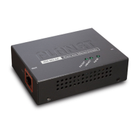
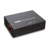
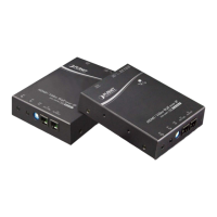
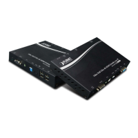
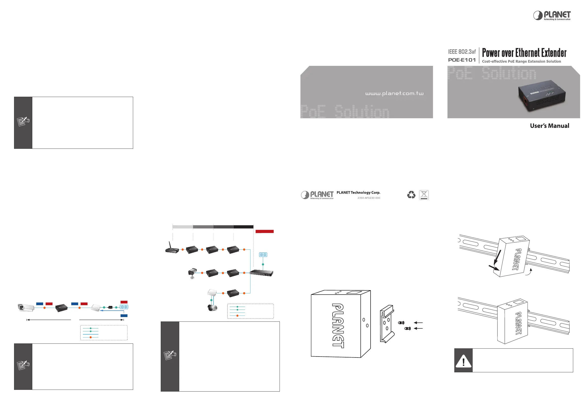
3.2 Connect POE-E101 to the Power Source
Equipment (PSE)
There are 2 RJ-45 ports in the PoE Extender, of which the
“IN” port functions as “PoE (Data and Power) input"
and the ”OUT” port on the other side functions as “PoE
(Data and Power) output”.
Step 1: Connect a standard Cat5e/6 UTP cable from
Power Source Equipment (PSE), such as PoE
Switch, PoE Injector hub and single port PoE
injector, to the “IN” port of POE-E101.
Step 2: The PSE delivers both Ethernet Data and PoE
power over UTP cable to the POE-E101 and the
“PoE IN” LED will be steady on.
1. The POE IN LED turn on steady green means
POE-E101 is being powered successfully with
PoE class 0.
2. If POE IN LED does not turn on, please
check the remote PSE or the cable with a
PC or a network device to see if the cable
is correct. Or with an 802.3af device such as
the target PD to check the power injection is
correct either.
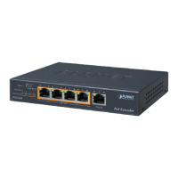
3.4 Multiple PoE Extender Installation
The POE-E101 PoE Extender supports multiple units, daisy-
chain installation. They can be employed in series for even
longer distances based on remote PoE IP Camera or PoE
WirelessAccessPointpowerrequirement.
Step 1: Connect the additional CAT5e/6 cable from the
“OUT” portofthe rstPOE-101, the otherendof
the UTP cable be used to connect to the “IN” port
of remote / next POE-E101.
Step 2: The “PoE OUT”LEDindicatoroftherstPOE-101
will be steady to shows it is providing power to
next PoE Extender.
Step 3: The “PoE IN” LED on the next POE-101 will
steady on.
Step 4: Connect the additional CAT5e/6 cable to the
remote PoE powered device to the “OUT” port of
next or third POE-E101.
3.3 Connect POE-E101 to the Powered Device
(PD)
Step 3: Connect the additional CAT5e/6 cable that will be
used to connect to the remote Powered Device
(PD) to the “OUT” port of POE-E101.
Step 4: The “OUT" port is also the power injectors which
transmit DC Voltage to the Cat5e/6 cable and
transfer data and power simultaneously between
the PSE and PD.
Step 5: Once POE-E101 detects the existence of an IEEE
802.3af device, the “PoE OUT” LED indicator will
be steady, ON to shows it is providing power.
PoE IP Camera PoE Injector
POE-E101
PoE Extender
PoE PoE
AC
+
Power
Data
Data
+
Power
Data
Power
100M100M
200M
DC
PoE
100Base-TX UTP with PoE
100Base-TX UTP
DC
Power Line (DC)
Power Line (AC)
AC
1. If the connected device is not fully
complying with IEEE 802.3af standard or
in-line power device, the PoE OUT LED
indicator of POE-E101 will not be steady on.
2. According to IEEE 802.3af standard, the
POE-E101 will not inject power to the cable
if not connecting to a standard IEEE 802.3af
device.
POE-E101
PoE Extender
PoE Ethernet Switch/
Injector Hub
PoE
PoE
PoE
PoE
PoE
PoE
PoE
PoE
PoE
100M100M100M
100M
100M100M100M
PoE Access Point
PoE IP Camera
non-PoE IP Camera
PoE Splitter
100M100M
DC
Power Output
300m 200m 100m 0m400m
AC
PoE
100Base-TX UTP with PoE
100Base-TX UTP
DC
Power Line (DC)
Power Line (AC)
AC
(11W)(9W) (13W) (15W)
POE-E101
PoE Extender
POE-E101
PoE Extender
POE-E101
PoE Extender
POE-E101POE-E101
1. Per POE-E101 will take 2 watts maximum
for the system itself, please check the total
power consumption of your 802.3af PD
and the POE-E101 before you make the
daisy-chain connection. If the overall power
consumption is overloaded, the local PSE
could shutdown the whole power system.
2. Per POE-E101 cable segment is limited in
100 meters Cat5e/6 UTP wire from its IN/
OUT port to the other data end, use of any
other non standard cable or over distance
could results in unstable connection.
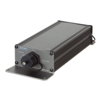
3.5 Optional - DIN-Rail mounting
There are two DIN-Rail holes on the left side of the POE-
E101 that allows the converter can be easily installed with
DIN-Rail mounting. The PLANET optional DIN-Rail mounting
Kit – RKE-DIN can be order separately. When need to
replace the wall mount application with DIN-Rail application
on the POE-E101, pleaserefer tofollowing gures to screw
the DIN-Rail on the converter. To hang the POE-E101, follow
the below steps:
Step 1: screw the DIN-Rail on the POE-E101.
Step 2: Lightly press the button of DIN-Rail into the track.
Step 3: Check the DIN-Rail is tightly on the track.
You must use the screws supplied with the
mounting brackets. Damage caused to the
parts by using incorrect screws would invalidate
your warranty.
 Loading...