operating manual BAIndustrie_UK 21
Only control systems and regulators approved by us may be
used. You can read about them in the catalogue or on our
current homepage. If other control systems or regulators are used,
then we cannot assume any guarantee or liability in the event of
destruction of the motor, regulator or the controller.
Motor connection cables must never be shortened or extendeds:
Firma Plettenberg Elektromotoren GmbH & Co. KG
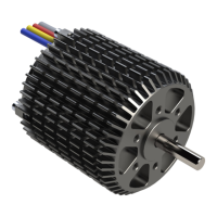
The three motor phases must be connected to the controller
according to the manufacturer's instructions:
The sensor cable must be connected to the controller in accordance
with the regulator manufacturer's specifications.
The brush-free Plettenberg motors with sensors are either equipped
with 3 hall sensors or with 3 fork light barriers with 120° electrical
angle. The sensors have open-collector outputs with pull-up
resistors. 6.2K Ohm pull-up resistors are normally installed, but
older motors can also have 10k Ohm or 12k Ohm pull-up resistors.
For motors with fork light barriers, no additional external pull-up
resistors may be used otherwise the output will not switch cleanly
to 0 V. The pull-up resistance can be easily determined by
measuring the resistance of the sensor VCC (red) against sensor
A (green) with an ohmmeter.
Phase A: red, Phase B: white, Phase C: blue/black
Sensor A: green, Sensor B: white, Sensor C: orange, VCC = 5 V:
red, GND = 0 V: black.
Temperature sensor NTC47K optional: blue
The shield of the sensor cable should be connected to the sensor
GND. The shield should not be connected to the motor housing or
motor control housing.
Commutation sequence forwards
Step1 Step2 Step3 Step4 Step5 Step6 Error1 Error2
Phase A(U)
+ Z - - Z + Z Z
Phase B(V)
Z + + Z - - Z Z
Phase C(W)
- - Z + + Z Z Z
Sensor A
1 1 0 0 0 1 0 1
Sensor B
0 1 1 1 0 0 0 1
Sensor C
0 0 0 1 1 1 0 1