3
Lay the communication cables of the inverters, meters, sensors and radio ripple control
receivers, if applicable, as well as the supply voltage from the enclosed power supply unit
into the lower connection area of the PL data logger (connection terminal 1+ 2). For the
supply cable into the connection area, you can optionally use the bendable openings in the
side of the housing.
Wire the green plug-in terminals included in the accessories with the supplied contacts
according to the connection diagram Figure 2.
Connect an active network cable to the Ethernet interface of the PL data logger.
Reconfiguration of a PL data logger
After successful wiring, supply the PL data logger with supply voltage via the power supply
unit according to the enclosed connection diagram. The PL data logger will now start.
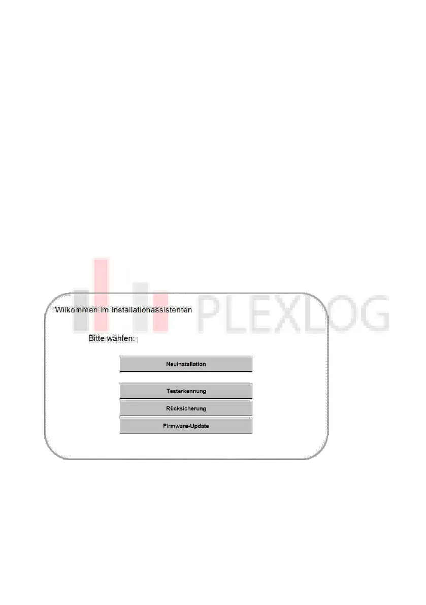
After booting, you will enter the installation wizard during initial startup.
Figure 3:
! Tip ! :