This document describes the Collins Youldon Hosereels – Hydraulic Rewind, an installation and maintenance manual (Technical Manual No SDM09H).
Function Description
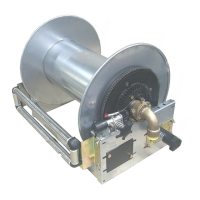
The Collins Youldon Hosereel is a device designed for the controlled deployment and rewinding of hoses, primarily using a hydraulic motor for power rewind. It can also be manually rewound in case of power failure. The hosereel is built around a central drum assembly supported by two bearings on its frame. A sprocket and chain drive connect the hydraulic rewind motor to the drum. The gooseneck and swingjoint assembly are located at one end of the hosereel, with the rewind mechanism potentially at either end of the drum. The gooseneck, depending on the fluid path size, can be an integral part of the center shaft or use separate castings.
The hydraulic control system for the hosereel includes a changeover valve, a flow control valve, and a three-position control lever with a pressure relief valve. The changeover valve directs hydraulic power to either the hosereel or a cargo pump. The flow control valve allows for pre-setting the maximum rewind speed during installation by adjusting the hydraulic oil flow to the motor. The three-position control lever manages the reel's operation:
- Position 2 (Freewheel): Allows the reel to freewheel during hose deployment, preventing over-running. An additional handwheel friction brake provides extra braking.
- Position 0 (Lock): Locks the reel to prevent the hose from shaking loose during transit.
- Position 1 (Rewind): Energizes the hydraulic motor to rewind the hose. This position has a spring return to Position 0.
A pressure relief valve sets the maximum rewind power, which must be adjusted during installation to ensure a safe maximum rewind torque.
Important Technical Specifications
General Construction:
- Frame: Made of two end plates joined by two tie plates.
- Drum Assembly: Centrally positioned, supported by two bearings on the frame.
- Rewind Mechanism: Hydraulic motor with sprocket and chain drive; also supports manual rewind via a cranked handle operating a crown wheel and pinion set.
- Finish: Supplied powder painted in standard colors, grey primer epoxy powder coat, galvanized, or stainless steel.
- Fluid Path: Inspected and tested before dispatch.
Dimensions (User-specified at delivery):
- Nominal width of hosereel drum: Options include 203mm, 305mm, 406mm, 457mm, 508mm, 610mm, 711mm, 813mm.
- Diameter of drum disks: Options include 432mm, 482mm, 508mm, 584mm, 736mm.
- Internal diameter of the fluid path: Options include 19mm (3/4"), 25mm (1"), 32mm (1 1/4"), 38mm (1 1/2"), 51mm (2").
Hydraulic Motor:
- Type: Danfoss OMM 32 (7640.OH.M ADAN AMM.32.P).
- Shaft: Ø16mm.
- Hydraulic System: Typically operates with a nominal 6 L/Min flow at 80 bar, with an excess flow (X-6) L/Min returned to the hydraulic fluid reservoir. Nominal 40 bar (40 kgf/cm²) for the hosereel hydraulic motor.
Swingjoint / Fluid Path Assemblies:
- 3/4", 1", 1 1/4" Swingjoints: External to the hosereel.
- Working Pressure: Up to 93 bar [1350 psi] for 3/4" and 1" (All Liquid & Gas Groups). Up to 60 bar [870 psi] for 1 1/4" (Liquid Groups 1 & 2 only) and 93 bar [1350 psi] (Liquid Group 2 only).
- Materials: Gunmetal and brass (some models gunmetal only).
- Seals: Nitrile seals (0216.00.T for 3/4", 0220.00.T for 1", 0326.00.T for 1 1/4").
- 1 1/2" and 2" Swingjoints: Formed from several cast items.
- Working Pressure: Refer to Pressure Equipment Directive 97/23/EC.
- Materials: Aluminium or Gun Metal.
- Seals: Nitrile 'O' ring (early models), Viton 'O' ring (early models), Chevron seal kit (current models).
Ancillary Devices (Optional):
- Fixed 4-way roller guides: Designed to reduce hose wear.
- Hinged roller guides: Designed to reduce damage to cabinet door seals and bodywork.
- Top tilt out roller guides: For easier hose deployment and storage.
- Inverted mounting kit: For mounting the hosereel upside down (factory-fitted).
- Earth continuity device: Where fitted, the installer must provide a continuity path.
- Swing out platforms: Requires rigid mounting points for bearings and support in the "parked" position.
- Remote Rewind: Requires adequate guarding for all moving parts and correct alignment of the rewind mechanism.
Usage Features
Installation:
- Mounting: Bolt the hosereel frame onto a flat, firm surface, using four flexible mounting pads to minimize distortion. Ensure the mounting is square and rewind gears are aligned if supplied without a frame.
- Space: Allow sufficient space for manual rewind handle rotation and for servicing/maintenance.
- Hose Connection: Connect the inlet to the swingjoint via a flexible hose to avoid strain or twisting. For 38mm (1 1/2") or 50mm (2") hose, remove the gooseneck, fit the hose, then refit the gooseneck ensuring the seal is correctly positioned.
- Protection: Install vehicle-mounted hosereels in a cabinet to protect gears, bearings, and chains from dirt and water.
- Hydraulic Motor Installation: Must be carried out by a competent technician. The pressure relief valve must be set to a safe maximum rewind torque.
Operation:
- Deploying the Hose: Ensure the manual rewind handle is removed and the brake is partially released (providing enough friction to prevent overrun). Pull the hose with a smooth, even movement. The hydraulic motor freewheels during deployment. Motors should not be used to deploy the hose.
- Rewinding the Hose (Manual): Return the nozzle to the hosereel. Swing open the handwind cover, fit the manual rewind handle, and check the brake is set for free drum rotation. Turn the handle with gloved hands, guiding the hose evenly. Once rewound, set the brake to prevent drum rotation and store the nozzle and handle safely.
- Rewinding the Hose (Hydraulic): Observe all warnings and cautions. Ensure the manual rewind handle is not fitted and the brake is correctly set. Operate controls as directed by the hydraulic system installer. Guide the hose evenly with gloved hands. Reduce speed as the hose is almost fully rewound. Set the brake after rewinding and store the nozzle safely.
- Ancillary Devices:
- Roller Guides: Hose should run smoothly between rollers. Take care not to trap hands. Hinged guides should be swung open for deployment and returned to the parked position after use. Top tilt-out guides require operating latches before pulling forward and pushing back.
- Swing Out Platforms: Release the spring bolt to open, secure, and return to the "parked" position after use.
Maintenance Features
Weekly Maintenance:
- Check and top up the hydraulic oil level in the reservoir.
Monthly Maintenance:
- Grease drum bearings and rewind mechanism spindle through grease nipples.
- Lubricate the drive chain sparingly.
- Release the brake and check for easy reel rotation.
- Inspect the hose for damage, deterioration, or swelling under pressure.
- If fitted, check the earth continuity device is functioning correctly.
Bi-annual Maintenance:
- Check all fasteners for tightness.
- Check for excessive free movement between frame bearings; adjust the support bearing position if needed.
- Remove the plastic guard, check handwind gear pinion and crown wheel alignment. Adjust the handwind spindle bracket and lubricate gear teeth if needed. Tighten nyloc nuts to at least 53Nm [40lb ft] and refit the guard.
- Check drive chain tension (13mm total side movement at midway position). Adjust by moving the rewind motor mounting plate and lubricate the chain.
- Examine hydraulic pipework for damage or leaks and repair as necessary.
- Check control valves for leaks and repair or replace faulty valves.
Corrective Maintenance:
- Hydraulic Rewind Motor Removal/Replacement: Loosen motor bracket nuts/bolts, slide assembly to remove chain. Remove fixings. Remove sprocket from shaft (use bearing extractor if tight, do not hammer). Refit in reverse order, ensuring 13mm chain movement.
- Swingjoint / Fluid Path Assemblies:
- Replacing Seals (3/4", 1", 1 1/4"): Drain hose, remove inlet hose (if necessary). Remove circlip and washer from stem, pull off sleeve. Remove old seals, clean parts, fit new seals, replace sleeve, washer, and circlip. Refit inlet hose.
- Replacing Swingjoint (3/4", 1", 1 1/2" LPG, 1 1/2" high pressure): Disconnect flexible hose from swingjoint, then swingjoint from hosereel. Fit new swingjoint with thread sealant, reconnect flexible hose, and check for leaks.
- Replacing Inlet 'O' ring or Chevron seal (1 1/2", 2"): Drain delivery hose, remove inlet hose. Remove 3 bolts and shakeproof washers securing inlet, pull off inlet to expose seal. Remove old seal, clean parts, fit new seal (O-ring in spindle groove, chevron in inlet). Apply grease, push inlet back, secure with bolts, reconnect hose, and check for leaks.
- Replacing Gooseneck &/or seal (1 1/2", 2"): Drain delivery hose, unwind fully. Remove 2 bolts/washers securing gooseneck. If replacing gooseneck, remove from hose, connect new gooseneck to hose with thread sealant. Remove old seal from groove, clean parts, fit new seal, refit gooseneck, and check for leaks.
- Replacing Bearing Housing (1 1/2", 2"): Drain delivery hose, isolate power supply (if rewind motor fitted). Unwind hose fully. Remove chain guard (if power rewind). Slacken chain by loosening 4 bolts on drive unit mounting flange. Support drum, remove 3 bolts/washers securing inlet to bearing housing, remove inlet. Remove 2 bolts/washers connecting bearing housing halves, lift off top. At opposite end, remove bolts securing bearing to frame, lift drum away. Remove nuts/washers securing bottom half of bearing housing, replace part. Lower drum, refit bolts, fit new bearing housing top. Refer to inlet seal replacement. Apply grease to seal mating parts, position inlet, secure with bolts. Reconnect inlet hose. Re-tension chain (13mm movement), tighten drive unit bolts. Refit chain guard. Check reel turns freely, adjust brake if needed. Fit rewind handle (or reconnect power supply), check rewind operation, and check for leaks.
Problem Solving:
- Drum does not rotate easily: Check handwind brake, lubricate bearings, check drive chain tension, check for twisted frame, check rewind gear mesh.
- Rewind is weak: Check hydraulic set pressure.
- Hydraulic drive not rewinding: Check hydraulic fluid flow, control lever position, pressure relief valve setting, hydraulic system, flow control valve, changeover valve. Replace motor if faulty.
- Product leakage: Check and replace worn seals in swingjoint. Replace defective swingjoint parts or assembly.