706303/081915/A Wireless Control System
6
4 INSTALLATION
WARNING!
Do not attempt installation of this unit unless you are
familiar with the necessary tools, equipment, utility
connections and potential hazards. Installation should
be performed only by a qualifi ed service provider.
Failure to do so could result in reduced performance
of the unit, serious personal injury or death.
WARNING!
Fire hazard
Never install the control box in areas with fl ammable
gases.
4.1 Unpacking
Check that the product is complete. The package should contain:
Article No. Description
704502 Wireless Receiver Unit with 18 AWG 4 conductor
prewired cable 10’ long, and antennae
704506 Wireless Transmitter Unit with Pressure Switch
(PC-500) and 2 conductor lead with .187 female
disconnect terminals installed
4.2 Electric connection
Connect the Wireless Control System in accordance with the
separately supplied electrical diagram.
CAUTION!
Electric connection to be executed in accordance with
local requirements. Ensure compliance with the EMC
regulatory arrangements.
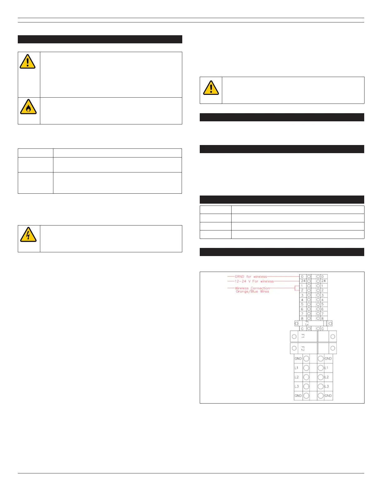
4.3 Primary Wiring Procedure
4.3.1 Wireless Receiver Wiring Connections
Connect the red wire labeled 12-24V to terminal 24V on terminal
strip TB1, connect the black wire labeled GRND to terminal 0 on
terminal strip TB1, connect the blue wire labeled C to terminal 1
on terminal strip TB1, connect the orange wire labeled NO to
terminal 2 on terminal strip TB1 inside OS-3 control box.
4.3.2 Wireless Transmitter
The Wireless Transmitter comes with 2 electrical leads which are
connected to a pressure and/or temperature switch used with
emergency response vehicle exhaust systems. When these
contacts are triggered a green light will illuminate on the front of
the transmitter. This light will indicate the unit is transmitting.
For other applications, an optional micro-switch for hose reel or
recoil balancer can be connected to the transmitter. Please
consult Plymovent for further details.
4.3.3 Programming the Wireless Receiver and
Transmitters
Step 1: Power unit on
Step 2: Locate the “Learn” button on top left corner of the circuit
board labeled SW1.
Step 3: Press the “Learn” button and the learn light will
illuminate.
Step 4: Locate the transmitter to be programmed and touch the
2 pigtail leads together. The “Learn” LED will fl ash and turn off.
The transmitter is now programmed.
Repeat steps above for additional transmitter units up to 24
total.
WARNING!
Procedures which, if not carried out with the
necessary caution, may damage the product and/or
cause serious personal injury.
5 MAINTENANCE
The Wireless Transmitter requires a Size 2032 battery to be
changed as needed.
6 TROUBLESHOOTING
If the Wireless Control System does not function correctly,
please fi rst verify that the batteries on the transmitters are
installed correctly and in good working order. If this does not
resolve the issue, then please contact your local authorized
dealer/technician.
7 SPARE PARTS
Article No. Description
704502 Wireless Receiver Unit only
704504 Wireless Transmitter Unit only
704000 PC-500 Engine Pressure Switch only
8 ELECTRICAL DIAGRAM
Please refer to Figures 8.1-8.2.
Fig. 8.1 Plymovent OS-3 Control Box Terminal Detail