OUT3 AS UNIVERSAL OUTPUT
Galvanically isolated from the inputs.
Freely scalable
Resolution: 11 Bit
Timeconstant of DA-transducer T90 50 ms
Limitfrequency of the whole continuous
controller > 2 Hz
Current output
0/4...20 mA configurable.
Signal range: 0...ca.21,5 mA
Max. load:
≤
500
Ω
Load effect: 0,02 % / 100
Ω
Resolution:
≤
22
µ
A (0,1%)
Accuracy
≤
40
µ
A (0,2%)
Voltage output (short-circuit proof)
0/2...10V configurable
Signal range: 0...ca.11 V
Min. load: ≥ 2k
Ω
Load effect: kein Einfluß
Resolution:
≤
11 mV (0,1%)
Accuracy
≤
20 mV (0,2%)
OUT3 used as transmitter supply
Output power: 22 mA /
≥
13 V
OUT3 used as logic output
Load
≤
500
Ω
0/
≤
20 mA
Load > 500
Ω
0/> 13 V
FUNCTIONS
Control behaviour
w
Signaller with adjustable siwtching
difference (ON/OFF controller)
w
PID controller (2-point and continuous)
Control parameters self-adjusting or manually adjustable via
front panel keys or BlueControl software.
Limit value functions
Monitoring is provided for: exceeded max., min. or max. and
min. limit value with adjustable hysteresis.
The following signals can be monitored:
w
Measured value
w
Process value
w
Control deviation
w
Control deviation with suppression after
start-up or set-point changes
w
Set-point
w
Correcting variable Y
Functions
w
Measured value monitoring
w
Measured value monitoring with storage.
Reset via front panel keys or digital input
w
Measured value change
w
Measured value change and storage
Several limit values and alarms can be combined by a logic OR
function and output e.g. as a common alarm.
ALARM + MAINTENANCE MANAGER
Displayof error messages, warnings and stored limit signallings
in the error list.
Messages are stored and can be reset manually.
Possible elements of the error list:
w
Sensor break, short circuit, polarity error
w
Self-tuning error
w
Stored limit values
- E.g. recalibration warning
(when exceeding an adjustable number of
operating hours, a message is displayed)
- E.g. maintenance interval of switching element
(when exceeding an adjustable number of
switching cycles, a message is displayed)
w
Internal errors (RAM, EEPROM, ...)
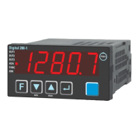
DISPLAY
Display
5-digit 19 mm LED
POWER SUPPLY
Dependent of order:
AC SUPPLY
Voltage: 90...260 V AC
Frequency: 48...62 Hz
Power consumption approx. 7,0 VA
UNIVERSAL SUPPLY 24 V UC
AC voltage: 20,4...26,4 V AC
Frequency: 48...62 Hz
DC voltage: 18...31 V DC
Power consumption: approx.. 7,0 VA
BEHAVIOUR WITH POWER FAILURE
Configuration, parameters
and adjusted set-points, con
-
trol mode:
Non-volatile storage in
EEPROM
BLUEPORT FRONT INTERFACE
Connection of PC via PC adapter (see
"Accessory equipment"). The BlueControl
Technical data
Digital 280-1 43