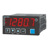
Connection of input di1 4
Digital input, configurable as switch or push-button
Connection of outputs OUT1/2 5
Relay outputs 250V/2A normally open with common contact connection
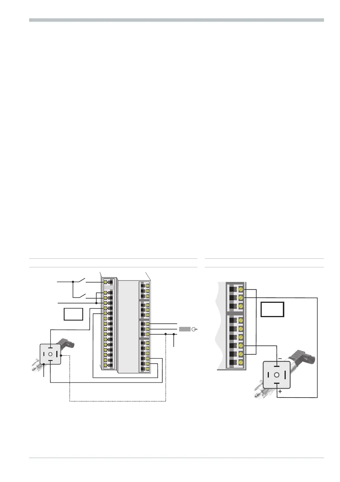
Connection of output OUT3 6
g logic (0..20mA / 0..12V)
h voltage (0/2...10V)
i current (0/4...20mA)
i transmitter power supply
Connection of inputs di2/3 7 (option)
Digital inputs (24VDC external), galvanically isolated, configurable as switch or
push-button
Connection of output U
T
8 (option)
Supply voltage connection for external energization
Connection of bus interface 9 (option)
RS422/485 interface with Modbus RTU protocol
a
If U
T
and the universal output OUT3 is used there may be no external galvanic
connection between measuring and output circuits!
Electrical connections
Digital 280-1 Terminal connection 7
Option
+24VDC
5mA
5mA
0V
1
2
3
K
+
-
+
-
+
-
17,5V
22mA
OUT3
J
J
x
1
7
5
8
6
9
10
11
12
13
14
15
4
3
5
1
7
5
8
6
9
10
11
12
13
14
15
4
3
(2)
17
16
78 di2/3, U
T
2-wire transmitter supply
1
2
3
K
+
-
+
-
13V
22mA
7
8
9
10
11
12
13
14
15
6 OUT3 transmitter supply