6
Programmable Microelectronics Corp. Issue Date: February, 2004, Rev: 1.4
PMC Pm25LV512/010
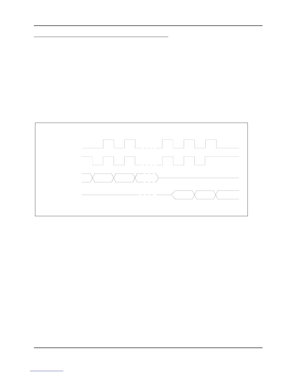
SPI MODES
These devices can be driven by microcontroller with its
SPI peripheral running in either of the two following modes:
Mode 0 = (0, 0)
Mode 3 = (1, 1)
For these two modes, input data is latched in on the
rising edge of Serial Clock (SCK), and output data is
available from the falling edge of Serial Clock (SCK).
The difference between the two modes, as shown in
Figure 2, is the clock polarity when the bus master is in
Stand-by mode and not transfering data:
- Clock remains at 0 (SCK = 0) for Mode 0 (0, 0)
- Clock remains at 1 (SCK = 1) for Mode 3 (1, 1)
Figure 2. SPI Modes
SCK
SCK
SI
SO
Mode 0 (0 0)
Mode 3 (1 1)
SERIAL INTERFACE DESCRIPTION (CONTINUED)