P-1500/P-1700-manual from PMV 14321-99.6
– 9 –
Fit the intermediate piece and
tighten the screw lightly.
Fig 23
Check that the bottom edge of
the intermediate piece is
slightly (0.5-1 mm) outside the
face in the casing.
Fig 24
Fit the valve body with spool.
Take care not to damage the
groove in the spool for the
balance arm.
Fit the screws with the
washers. Press the valve body
against the inter-mediate
piece. Back off I the screw.
Press hard and tighten the
screws. Tighten the screw.
Fig 25
Adjust the starting point by
means of the screw.
Fig 26
5. To replace the bellows
Remove the cover. Remove
the spring with its adjusting
nut and spring guide by
compressing the spring. Rem-
ove the screws and remove
the balance arm. Turn the
bellows back and forth while
with-drawing it out of its
mounting.
Before fitting, the length of
the bellows must be
measured. The length should
be 35mm and should be
adjusted if necessary by stret-
ching or compressing the
bellows.
Check that the O-ring is in
good condition and take care
when compressing the
bellows while fitting it into
place.
Fig 27
N.B. Hold the part of the
bellows to which the O-nng is
fitted when pressing in the
bellows, since the dimension
35 mm may otherwise alter.
Refit the balance arm and the
spring.
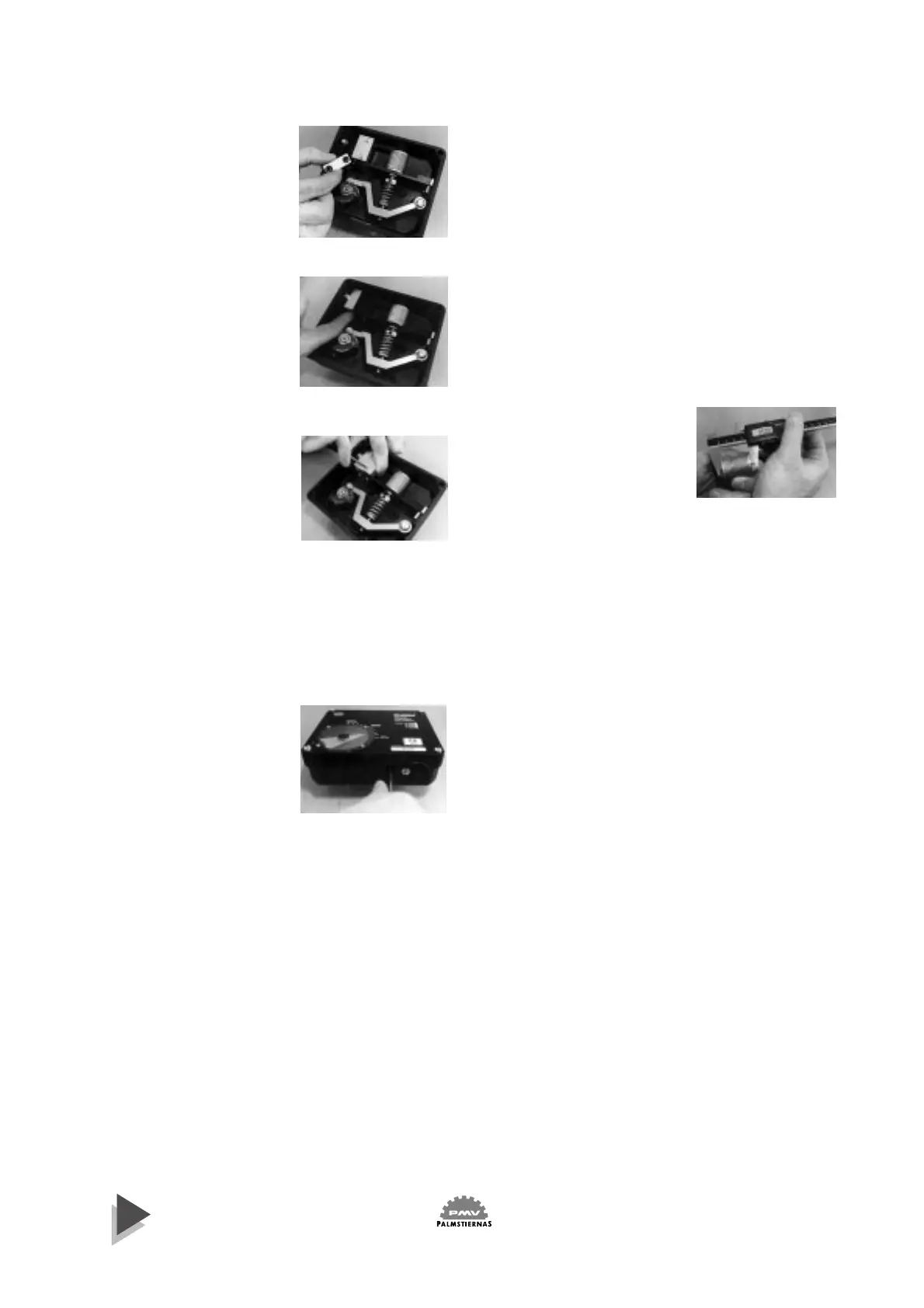
6. To zero the indicator
Remove the four screws and remove the cover.
Back off the locking screw and zero the indicator.
Replace the cover to check the setting of the indicator.
Make fine adjustments if necessary.
Tighten the locking screw. Do not tighten screw too
hard, otherwise the indicator will crack.
Mount the cover and tighten the four screws.
Figure 23
Figure 24
Figure 25
Figure 26
Figure 27


 To Next Page
 Loading...