8
Pub. No. OM-A-10H REV. 7 — June 2006
FEATURES
• LCD screen indicating right/left tower drying, right/left
tower regenerating, tower switching, actual sequence
time, demand cycle indication (opt.), fail to shift alert
(opt.)
• LED sequence annunciator indicating R/L tower
drying/regenerating, demand cycle indicator (opt.),
high humidity alarm (opt.), fail to shift alarm (opt.)
• Timer and setting memory
• Time cycle advance button
• 5 or 10 minute NEMA cycle selector
• Open thermocouple protection
MODE OF OPERATION:
1.
START UP:
The Digital Microprocessor Controller
will start to operate as soon as power is supplied
and the unit is turned on. The load outputs will
recycle on and off based on a 5 minute or a 10
minute NEMA cycle. The sequence will proceed
according to the Sequence of Operation Diagram
SDG-2. The point of the sequence at which the
timing starts depends on where the cycle stopped
when power was last turned off.
2.
MANUAL CYCLE ADVANCE:
The backside of the
remote I/O module contains an “ADVANCE” push
button. Each time the “ADVANCE” push button is
pressed, the timing cycle advances by 30 seconds.
The “ADVANCE” push button is disabled whenever
the timing is stopped by an inhibit switch.
3.
NEMA CYCLE:
The DMP Controller can be set to
operate in a 5 minute NEMA Cycle or a 10 minute
NEMA Cycle. The cycle can be selected via a slide
switch at the back of the remote I/O module.
4.
RELAY OUTPUTS (DRY CONTACTS):
There are
two relay outputs for remote annunciation. The
output is normally open and rated for 10 AMPS
resistive at 125VAC, 5 AMPS resistive at 30VDC.
The outputs are for the failure to switch and high
humidity alarms. If one or both inhibits are made, the
relays will be energized and the LED on the remote
I/O will light up.
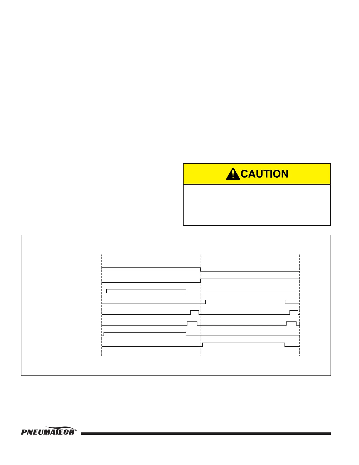
FIGURE 2 — SDG-2: 10 MINUTE SEQUENCE OF OPERATION DIAGRAM
This unit may be damaged by electrostatic
discharge. Follow procedures for static
sensitive parts when handling, shipping or
installing this unit.
1
LEFT TOWER
SWITCHING
ON
OFF
ZERO
ZERO
300 SECONDS
300 SECONDS
600 SECONDS
600 SECONDS
2
RIGHT TOWER
SWITCHING
ON
OFF
3
LEFT TOWER
REGENERATING
ON
OFF
4
RIGHT TOWER
REGENERATING
ON
OFF
5
DEMAND
CYCLE
ON
OFF
6
REPRESSURIZING
ON
OFF
7
LEFT TOWER
DEPRESSURIZING (OPT.)
ON
OFF
8
RIGHT TOWER
DEPRESSURIZING (OPT.)
ON
OFF