12 Pub. No. OM-A-10H REV. 7 — June 2006
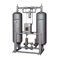
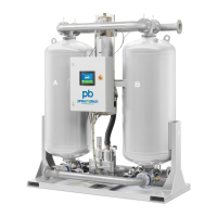
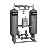
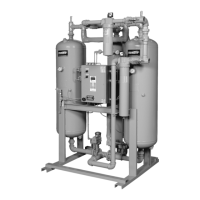
PHM MINI SERIES HEATLESS AIR DRYER
INSTALLATION & OPERATION
General
1. If base mounted, secure base plat to hard surface, or
hang securely on a wall.
2. Dryer should be installed indoors, or under a shed.
3. Equip the dryer with inlet and outlet isolation valves
and a bypass valve for ease of servicing and
start-up.
4. Connect electric power to the dryer through a
properly sized fused disconnect switch.
5. Reactivation exhaust may be piped away from the
dryer, making sure proper pipe size is used. For
every ten foot run, increase the pipe diameter by one
size to reduce back pressure.
6. ELECTRICAL CONNECTIONS: Follow the
recognized electrical codes with local and municipal
codes for electrical connection. All components must
be load rated as approved by NEC, NEMA, CSA
and UL.
7. During shipment wire connection may become loose.
Per U.L. specification, torque screws inside enclosure
to 20 in-lbs.
8. GROUNDING: It is mandatory that the dryer be
grounded. Use an adequate ground with the
conductor sized to NEC.
9. STORAGE: In case of extended storage period
before the installation, follow these simple
procedures:
a. Seal or cover all the parts
b. Wrap the electrical enclosure
c. Wrap the mufflers
d. If the desiccant is shipped loose, store it inside to
avoid any rain or water damage.
10. LEAK TEST: All the dryers are tested at the factory
for any leaks before shipment. An air leak could
develop during transportation or installation.
Pressurize the system and check for any leaks.
Theory of Operation
The Pneumatech PHM Mini Series Heatless Regenerative
Air Dryer features “State of the Art” design. The 4-Way
Inlet valve & outlet shuttle valve make these dryers trouble-
free in operation and require very little maintenance.
Standard Heatless Regenerative Air Dryers operate on a
10 minute NEMA cycle.
• Drying: 5 minutes
• Regeneration: 4 minutes, 20 seconds
(continuous flow)
• Repressurizing: 40 seconds
While one absorbent filled tower is drying the inlet flow at
the line pressure, in the upward direction for 5 minutes,
the other tower goes through a mode of desiccant
regeneration in counter flow for 4 minutes, 20 seconds.
Start-Up Procedure
1. Leave the dryer power supply disconnected.
2. Keeping the dryer isolation outlet valve closed,
slowly pressurize both the desiccant chambers to line
pressure.
3. Check for any leaks in the system.
4. Purge valve should be closed at this time (N.C.
Valve).
5. Connect the dryer power supply.
6. The purge valve should open and depressurize one
desiccant chamber.
7. Run the dryer through one or two cycles before
slowly opening the dryer isolation outlet valve.
Operational Observation
1. The drying chamber should be at the line pressure
indicated on the drying chamber pressure gauge.
2. The reactivation chamber should be at 0 PSIG. (Any
higher pressure is an indication of some malfunction,
refer to Troubleshooting Guide on Page 21.)
3. The standard time cycle is 10 minutes. While one
chamber is drying for 5 minutes the other chamber
goes through a mode of desiccant reactivation and
purge for about 4.3 minutes. The purge exhaust
valve then closes to allow the chamber to
repressurize to line pressure before switch-over
occurs at the end of 5 minutes.