Drilling the holes for the electrical
supply cable entry
As the electrical supply to the Pod Point Solo may be fed
from a number of directions; the unit has been designed
to accept supply cable entry on either the left, right,
bottom or via rear entry “knockouts” The installer should
drill a suitable size hole for the cable and grommet/
gland to be used. Cable entry holes should not be
drilled on any curved surfaces as this may provide an
entry point for water. 20mm “Rear Knockouts” are also
provided, water tight ttings should be used. Cable entry
at the top of the unit is strictly prohibited.
When drilling the case:
1. Only drill in the at surfaces provided on the left, right,
bottom or rear of the unit. Do not drill on any curved
surface.
2.Take care not to damage any wiring or components
inside the case. Place a suitable stop (e.g. block of
wood) inside the case when drilling to prevent
accidental damage.
3. If any of the wiring or components are damaged
during installation DO NOT CONNECT OR SWITCH ON
THE POWER before consulting with Pod Point.
4. The wall can now be drilled for the 3 mounting holes,
Do not drill with the Pod Point in position as masonry
dust may cause latent damage to the unit.
5. The Pod-Point can now be tted to the wall, depending
on the wall structure solid/dry lined or stud partition,
appropriate xings must be used to secure the unit.
6. Once tted in place, the rear unit should be securely
xed ush to the wall.
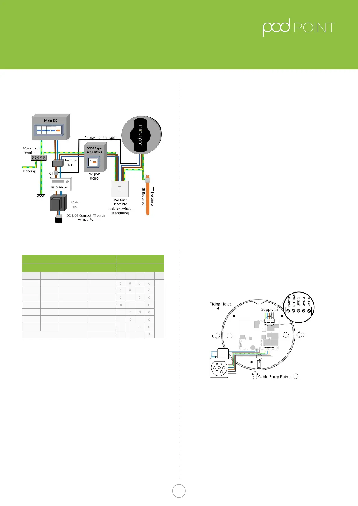
Wiring up the Pod Point solo
Fig.5
Solo Wiring Diagram
• With the rear unit securely tted to the wall, the
electrical supply connection can be made.
• As the installation route of the wiring will vary with
each Installation, allow enough cable to allow easy
termination so that the cable terminals are not under
strain.
• The choice of entry point used will determine the
amount of insulation/SWA that needs to be
removed for the internal wiring connection of the unit.
The diagram above illustrates the connection terminals
for the electrical supply cables.
Pod Point Solo Unit
Installation Guide
Pod Point Solo Install Guide
3
Table A.
Circuit protection and Power rating settings
Fig 4.
Typical Schematic of installation circuit
*The Pod Point also provides internal over-current protection in addition
to the above
Cable CSA
Power Rating
1Phase
3.1kW
2.4kW
1.4kW
MCB * / RCBO
Switch Setting
13Phase 432
6kW
4.8kW
3.7kW
Pod Disabled
7.2kW
9.4kW
7.2kW
4.3kW
18kW
14.4kW
11kW
21.6kW
16A
16A
10A
32A
32A
20A
40A
1.5mm
2
1
1
1
1
1
1
1
1
1
1 1 1
6mm
2
- 10mm
2
4mm
2
- 6mm
2
2.5mm
2
- 4mm
2
2.5mm
2
2.5mm
2
4mm
2
- 6mm
2
Unit Power RatingCircuit Protection
5**
Position depends on socketed/tethered
0=OFF, 1=ON
**Switch 5 OFF for socketed units
Switch 5 ON for tethered units
Pod Point January 2019
PP-D-130012-14

 Loading...