INSTALLATION
• The MX602 is designed for indoor use. Never use in a location where the unit may get
wet.
• NEVER
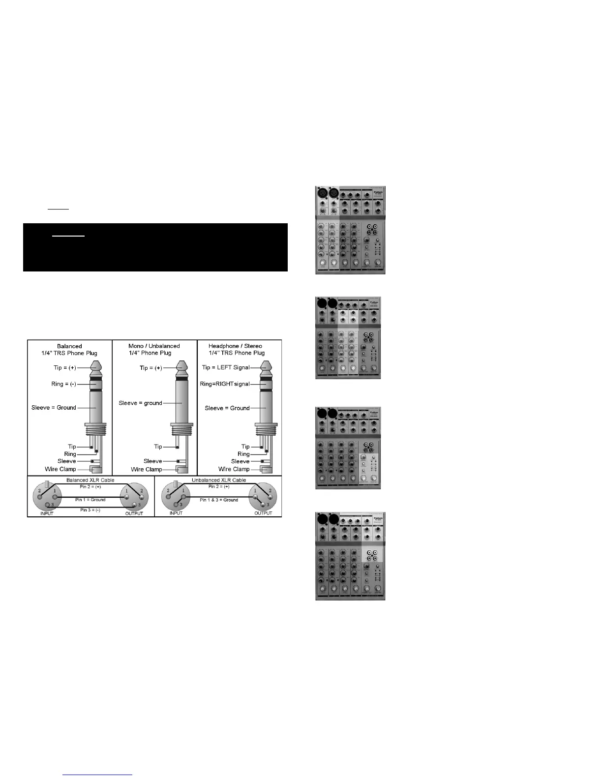
CONNECTOR WIRING
defeat the safety ground provision of the IEC power cord.
You will need many cables to complete the installation. Many more will be required for signal
patching during sessions. Pre-fabricated cables may not always fit your needs and sometimes
onsite repairs are necessary. The following illustrations show the correct connector wiring.
10
MONO MIC / LINE INPUT CHANNELS (1 - 2) DETAILS ON PG 4
There are two identical MONO input channels located
on the left of the console. These channels are
organized vertically. At the top is an XLR microphone
(MIC) input jack. 48V “phantom” power is available for
condenser MICs. Next is a ¼” Tip Ring Sleeve (TRS)
line level (LINE) input phone jack. Each MONO channel
can be used as either a MIC or LINE input. The other
controls provide a wide variety of sound shaping, signal
routing, external processing and gain adjustments.
STEREO INPUTS (3/4 - 5/6) DETAILS ON PG 5
There are two STEREO inputs (4 mono channels). The
line level inputs are balanced ¼” TRS phone jacks.
These channels are organized just like the “MONO
MIC/LINE” channels and have the same controls and
capabilities. However, no MIC inputs are provided.
MAIN SECTION DETAILS ON PG 8
After all sources have been selected, equalization set
and effects loops created, all signals are summed onto
the LEFT/RIGHT MAIN bus and/or the AUX bus. There
are numerous routing options from this point forward.
Here, you will find controls for the “MAIN MIX” level, AUX
return level and “PHONES/CONTROL ROOM” level.
INPUT / OUTPUT CONNECTIONS DETAILS ON PG 9
Here you will find all remaining input and output
connections. This is where the MX602 interfaces with
the rest of the studio.
3