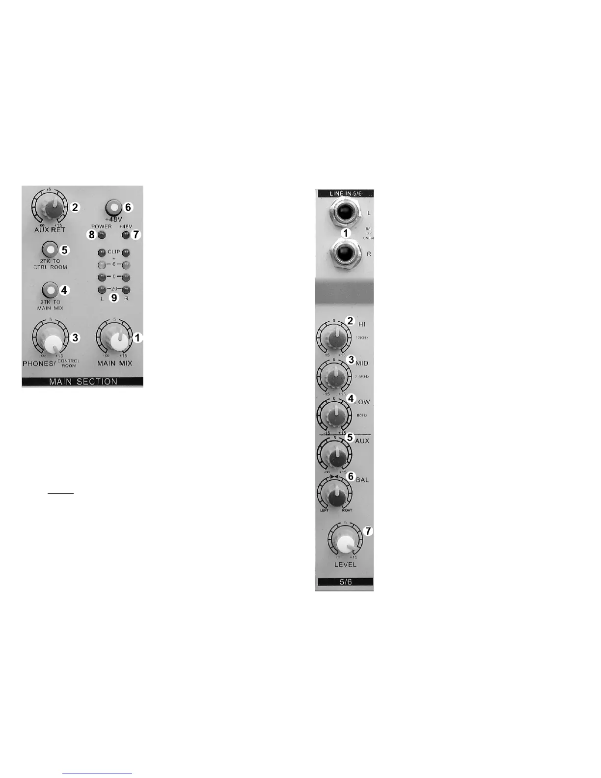
MAIN SECTION
① MAIN MIX LEVEL
η
All signals sent to the LEFT and RIGHT
MAIN bus are combined and sent to the
MAIN OUTPUTS. This control adjusts
the LEFT/RIGHT MAIN OUTPUT level.
② AUX RETURN LEVEL
η
The “STEREO AUX RETURN” is added
to the LEFT/RIGHT bus. This control
adjusts the level of the “STEREO AUX
RETURN” signal added to the
LEFT/RIGHT bus.
③ PHONES / CONTROL ROOM LEVEL
Adjusts the level of the signal applied to
the control room and headphone
outputs.
④2TK TO MAIN MIX (2 Track to Main Mix)
Press to send the TAPE input directly to
the LEFT/RIGHT bus (MAIN MIX).
Typically used for playback monitoring
or adding pre-recorded elements to the
mix.
⑤ 2TK TO CTRL ROOM (2 Track to Control Room)
Press to send the TAPE input directly to the CONTROL ROOM AND
HEADPHONE outputs. Typically used for real-time tape monitoring without
disturbing the ongoing performance.
⑥ +48V
Condenser microphones require an external power supply to operate.
Depressing this switch activates an industry standard 48V “phantom” supply.
• When the phantom supply is on, +48V is applied to both of the
microphone connectors. You may use either dynamic or condenser
microphones while the “phantom” power is on.
•
NEVER
⑦ +48V LED
use a balanced XLR to unbalanced ¼” phone adapter
when the phantom power is on!
This blue LED lights whenever the 48-volt microphone phantom power is on.
⑧ POWER LED
This red LED lights whenever the console is on. The MX602 is on whenever
the external power supply is connected to the console and plugged into a wall
outlet.
⑨ LED VU METER
These LEDs indicate the signal level of the MAIN MIX. For best results, avoid
operation above 0dB. Occasional flashing of the +6dB LED may be allowable
but operation with the “CLIP” LEDs flashing must be avoided.
8
STEREO INPUT CONNECTIONS AND CONTROLS
① LINE IN 4/5 – 5/6 (L)
Balanced line level input, ¼” phone jack, Tip Ring Sleeve
(TRS). LEFT channel. NOTE: When only the “L” input jack
is used, the signal is routed to both left and right channels
(MONO).
η
LINE IN 4/5 – 5/6 (R)
Balanced line level input, ¼” phone jack (TRS). RIGHT
channel.
② HI EQ
Adjusts high frequencies up or down. Set to 0 (center
detent) for no EQ.
③ MID EQ
Adjusts mid frequencies up or down. Set to 0 (center
detent) for no EQ.
④ LOW EQ
Adjusts low frequencies up or down. Set to 0 (center
detent) for no EQ.
⑤ AUX
η
Adjusts the signal level sent to the AUX bus. This control
“AUX” is after, or
POST “LEVEL”
⑦
. This means “LEVEL”
adjustments will also change the signal level being sent to
the AUX bus.
⑥ BAL
Adjusts the relative LEFT / RIGHT signal level (BALANCE)
applied to the LEFT/RIGHT MAIN bus.
⑦ LEVEL
This is a compact mixing console. To reduce the console
size, rotary knobs are used in place of the familiar slider.
The function of the “LEVEL” control is the same as a linear
FADER. Use the “LEVEL” control to “fade” the channel in
or out during the performance. Normally this control should
be at the 12:00 position, This is not a volume control.
5
 Loading...