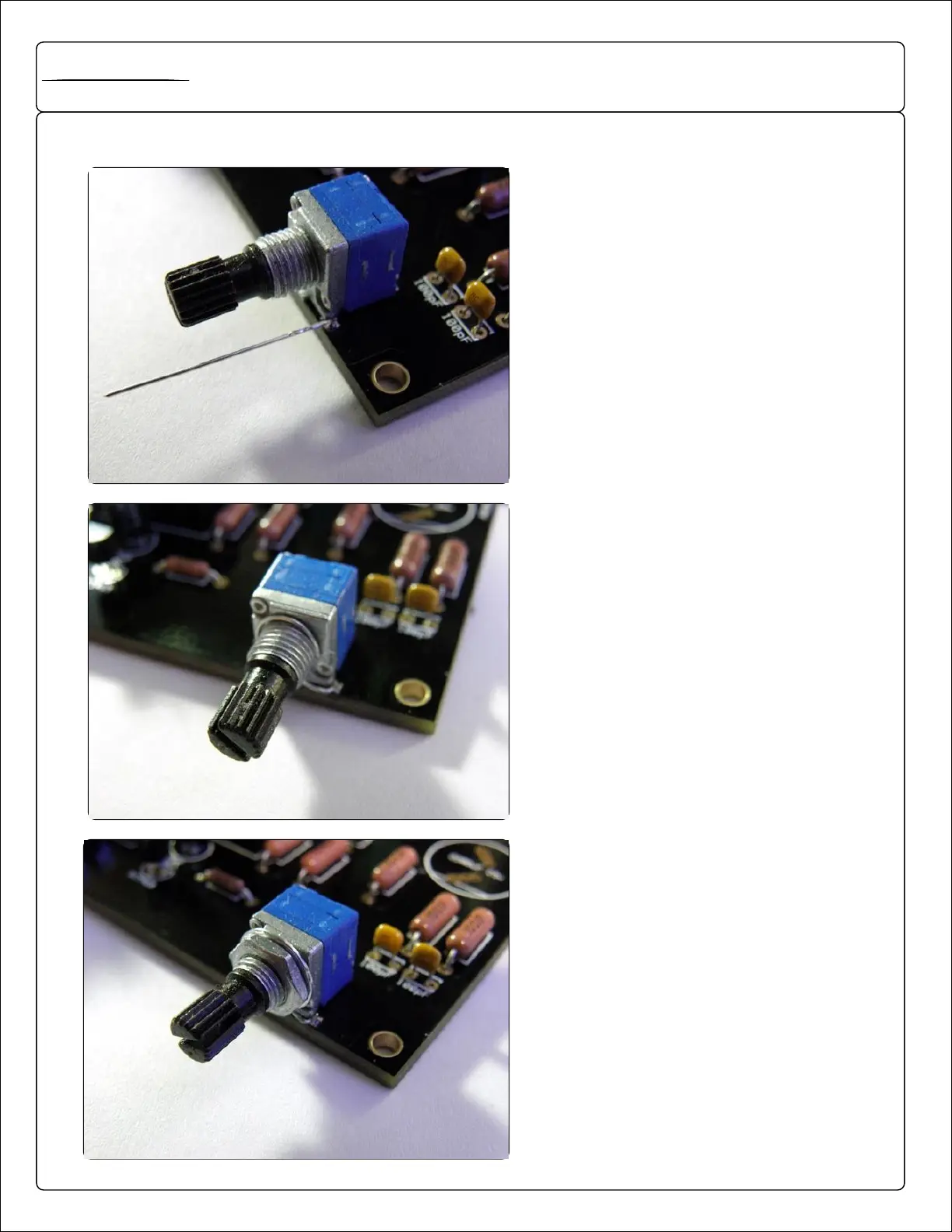
EasyManua.ls Logo

Polaris Project User Manual

Polaris Project
12 pages
To Next Page IconTo Next Page
To Previous Page IconTo Previous Page
Page #8 background image
VOLPOT GROUNDING
GROUNDING THE VOLUME POTENTIOMETER IS REQUIRED AS
WITHOUT IT, THE AMPLIFIER MAY BE SUBJECTED TO NOISE /
INTERFERENCE.
THE IMAGES ARE OF THE PREVIOUS GENERATION SUNRISE,
HOWEVER THE GROUNDING PRINCIPAL IS EXACTLY THE SAME.
FIRST, INSERT A WIRE LEAD INTO THE RIGHT SIDE VIA NEXT TO THE
VOLPOT AND SOLDER IN PLACE.
WRAP THE WIRE LEAD AROUND THE THREADED PORTION OF THE
VOLPOT AS SHOWN.
PUT ON WASHER AND NUT INCLUDED IN THE KIT. ONCE TIGHT, THE
VOLUME KNOB MAY BE INSTALLED.
Project
Polaris
Project
Polaris
Question and Answer IconNeed help?

Do you have a question about the Polaris Project and is the answer not in the manual?

Polaris Project Specifications

General IconGeneral
BrandPolaris
ModelProject
CategoryAmplifier
LanguageEnglish

Summary

Project Polaris Safety Information

Assembly and Operation Warnings

Highlights potential dangers from assembly errors, capacitor installation, and initial power-up procedures.

Project Polaris Specifications and Operational Guide

Technical Specifications

Details electrical and performance characteristics, including power, resistance, and frequency response.

Normal Operation and Notes

Guidance on startup, protection circuit behavior, volume control, and potential noise sources.

Project Polaris Assembly Preparation

Required Assembly Tools

Lists essential tools and materials needed for building the Project Polaris amplifier kit.

Soldering Techniques and Solder Joints

Provides guidelines for proper soldering, including cleaning leads and achieving quality joints.

Project Polaris Chassis Assembly

Bottom Chassis Preparation and Final Assembly

Instructions for assembling the chassis, attaching the PCB, and initial power-up checks.

Project Polaris Component Layout

PCB Component Identification

Diagram illustrating the placement of components on the Project Polaris circuit board.

Project Polaris Assembly Step 1

Populating Small Components

Instructions for installing small components like resistors, diodes, and capacitors onto the PCB.

Project Polaris Assembly Step 2

Populating Mid-Size Components

Guide for installing mid-size components, including polarized capacitor orientation and heatsink attachment.

Project Polaris Assembly Step 3

Volume Potentiometer Grounding

Detailed instructions for grounding the volume potentiometer to prevent noise and interference.

Project Polaris Assembly Step 4

Populating Large Components and Headphone Jack

Instructions for installing large components such as capacitors, TO263 diode, and the headphone jack.

Project Polaris Configuration Options

Understanding Jumper Settings

Explains how jumper settings customize input attenuation, bandwidth, gain, and output resistance.

Project Polaris Parts List

Component Breakdown

Detailed list of all resistors, capacitors, transistors, diodes, and other components required for the kit.

Related product manuals