22
Connection to the video signal terminals
Connection to the RGB signal terminal
1. Input signals
2. Signal input jacks
1. Input signals
2. Signal input jacks
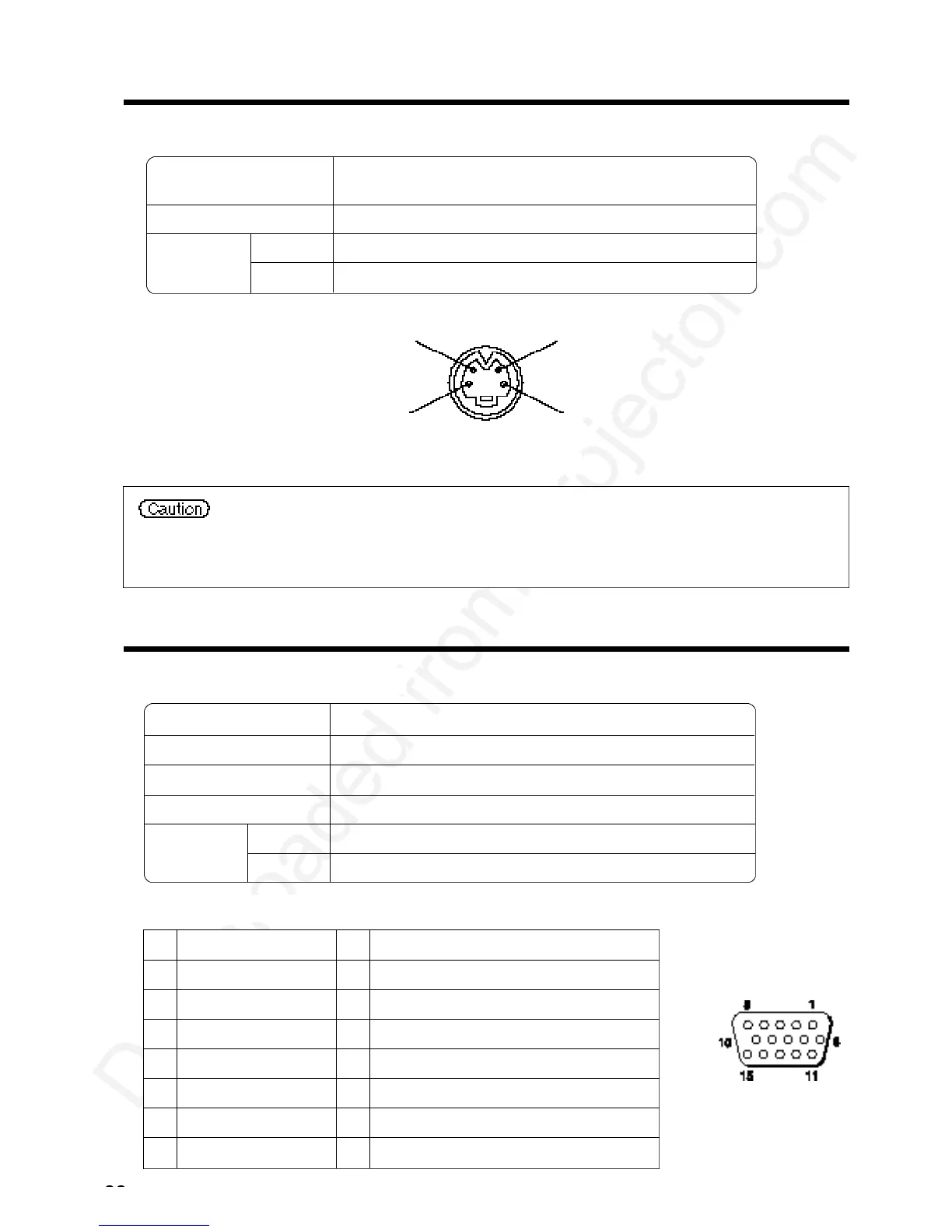
S-VIDEO input (mini DIN 4-pin)
Color signal
Ground Ground
Brightness signal
The priority sequence of the video input jacks is as follows.
(1) S-VIDEO input jack (2) RCA jack input jack
When video signals are being projected, the audio input by the video is output to the audio
output jack (RGB/VIDEO).
D-sub 15-pin
shrink jack
Video signal Analog, 0.7V p-p, 75 Ω terminator (positive polarity)
Horizontal sync signal TTL level (positive/negative polarity)
Vertical sync signal TTL level (positive/negative polarity)
Compound sync signal TTL level
Audio signal
Input 200mV rms, 20k Ω or less (max. 3.0V p-p)
Output 0~200mVrms,1k Ω
1 Video input (red) 9 N.C
2 Video input (green) 10 Ground
3 Video input (blue) 11 N.C
4 N.C 12 DDC jack (Display Data Channel)
5 N.C 13 Horizontal sync signal/compound sync signal
6 Ground (red) 14 Vertical sync signal
7 Ground (green) 15 DDC jack (Display Data Channel)
8 Ground (blue)
S-VIDEO signal
VIDEO signal
Audio signal
Input
Output
Brightness signal 1.0V p-p, 75 Ω terminator
Color signal 0.286V p-p (burst signal), 75 Ω terminator
1.0V p-p, 75 Ω terminator
200mV rms, 20k Ω or less (max. 3.0V p-p)
0∼200mVrms,1k Ω
 Loading...