33
A/V Board Removal and Replacement
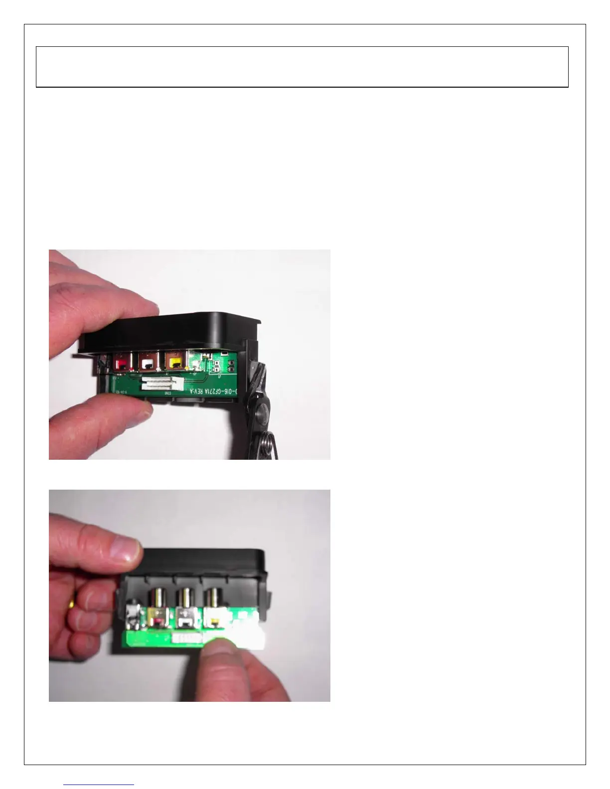
1. Disassemble rear cabinet and remove A/V assembly.
2. Using a small pair of wire cutters grip the side locking tab and pivot back towards the A/V
cable connector (PIC1). Locking tab should only pivot about 45 degrees. Do the same
for the opposite side of the A/V assembly.
3. Slide out A/V board and replace (PIC2).
4. Push locking tabs in to secure replaced A/V board.
PIC1
PIC2
6. A/V Board and Front/Side Control Button Disassembly
 Loading...