Do you have a question about the Polon-Alfa G-40 and is the answer not in the manual?
Mounting the PG-40 base industrial footing on ceilings or steel strings.
Methods for installing the G-40 base on different ceiling types.
Details the mounting procedure for the OZ-40 protection cover.
The G-40 Detector Base and PG-40 Base Industrial Footing are components designed for fire detection systems, specifically for connecting detectors within conventional or addressable control panels. These devices are manufactured by Polon-Alfa and comply with the AT-0112-0298/2011 Technical Approval and Certificate of Conformity No. 2789/2011 issued by the Scientific and Research Centre for Fire Protection (CNBOP). The manufacturer's website, www.polon-alfa.pl, provides access to the Certificate of Conformity, and a national declaration of compliance (No. 2PI/E287/2011 dated 15.12.2011) is available upon request.
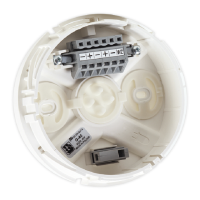
The G-40 detector base serves as a connection point for 40 model range detectors in conventional control panels and 4043 and 4046 model range detectors in the POLON 4000 series addressable control panels. It is primarily designed for dry ceiling mounting. The base facilitates the connection of fire detection line wires, which can be routed either on the wall plaster (surface mounting) or under it (semi-flushed mounting) within a special duct with a maximum height of 10 mm.
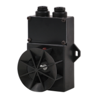
The PG-40 base industrial footing is an additional component used when the G-40 base is installed on a ceiling prone to steam condensation or mounted on horizontal suspension strands. This footing is designed for surface mounting, connecting to detection line wires placed inside a duct with a maximum external diameter of Ø18 mm.
For suspended installations, the G-40 base can be used with the PG-40 base industrial footing, equipped with a PG7 sealing gland and a PSGW ceiling suspended base. The suspended part of the base should be mounted on a 4-cord cable of 2 x 2 x 0.8 size. Both the PG7 sealing gland and the PSGW ceiling suspended base are optional accessories and must be ordered separately.
In environments where mechanical damage is a risk (e.g., sports halls or low rooms), the OZ-40 protection cover is recommended. Additionally, an optional P-40 special masking ring can be used to conceal the visible part of the base, though it is not applicable when the G-40 base is mounted in the PG-40 industrial footing.
The G-40 base is made of white plastic, with other colors available upon request. It comprises a body with a main connector featuring self-clamping latches for detection line wires and an additional connector for wire screens. The PG-40 base industrial footing is a homogeneous molding, also made of white plastic, with other colors available. It can optionally be equipped with a PG7 sealing gland.
The G-40 base offers versatile installation options depending on the mounting surface:
For wire connection, a flat screwdriver (max edge width at 3.5 mm) should be pushed into the connector hole. A short, bended WAGO type screwdriver (3.5 x 0.5 mm, cat. No. 210-258, available from POLON-ALFA) is recommended. Wire screens should be inserted into the additional connector and then placed between the rails inside the rectangular hollow of the base.
The PG-40 base industrial footing should be mounted on the ceiling with two screws and Ø6 mm extension anchor bolts, using a 127 mm hole spacing pattern to prevent deformation when screws are tightened. Alternatively, it can be installed on a horizontal steel string (Ø8 mm diameter recommended) using clamping bands.
For suspended installations using the PG-40, a Ø13mm hole must be drilled in the detector body for the PG7 sealing gland, accommodating a cable of max Ø7 diameter. The PSGW ceiling suspended base is used for ceiling mounting in this configuration.
The OZ-40 protection cover is mounted on the ceiling with two screws and Ø8 mm expansion anchor bolts, with a bolt hole spacing of 124 ± 4 mm. The base is then fixed to the cover with two M4 nuts, and the grating is fastened with three M4 x 10 nuts after the detector is installed.
The G-40 bases are designed to interoperate with POLON 4000 system control panels and conventional control panels. Line continuity in a detection line is achieved only when all detectors are placed in their bases. If a detector is absent, continuity can be maintained by placing the E287-04.00 jumper (an optional, separately ordered component) into the detector connector.
The G-40 base and its industrial footing require no servicing after installation, as they are continuously monitored by the fire alarm control panel. Periodical inspections of these components are conducted simultaneously with the routine maintenance of the detectors.
Users are advised to read the manual carefully before assembly and operation to prevent harm or legal violations. Polon-Alfa disclaims responsibility for damages resulting from inconsistent use. The product contains parts that can be dangerous; waste products should be disposed of at designated electric and electronic equipment collection points. The manufacturer reserves the right to change product specifications without prior notice.
| Brand | Polon-Alfa |
|---|---|
| Model | G-40 |
| Category | Security Sensors |
| Language | English |