8Polycom Ceiling Microphone Array Setup Sheet
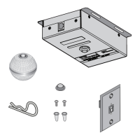
Polycom Ceiling Microphone Array Extension Kit
.6 m (2 ft)
2457-26759-024
7.5 m (25 ft)
plenum crossover
(Use between two electronics enclosures.)
2457-24009-001
Second 7.5 m (25 ft)
plenum crossover
(Use between second and third electronics
enclosures for TPX HD 306M, Version 2.0
and later only.)
2457-24009-001
If your ceiling is 3.05 m (10 ft) or higher, you
should order an optional 1.82 m (6 ft) drop
cable (2457-26764-072 for black or
2457-26765-072 for white) for each Ceiling
Microphone Array.
If you are creating your own cables, refer
to the Integrator Reference Guide for your
product for cable pin-outs at
http://support.polycom.com. Ensure that the
cables meet all local building code regulations.
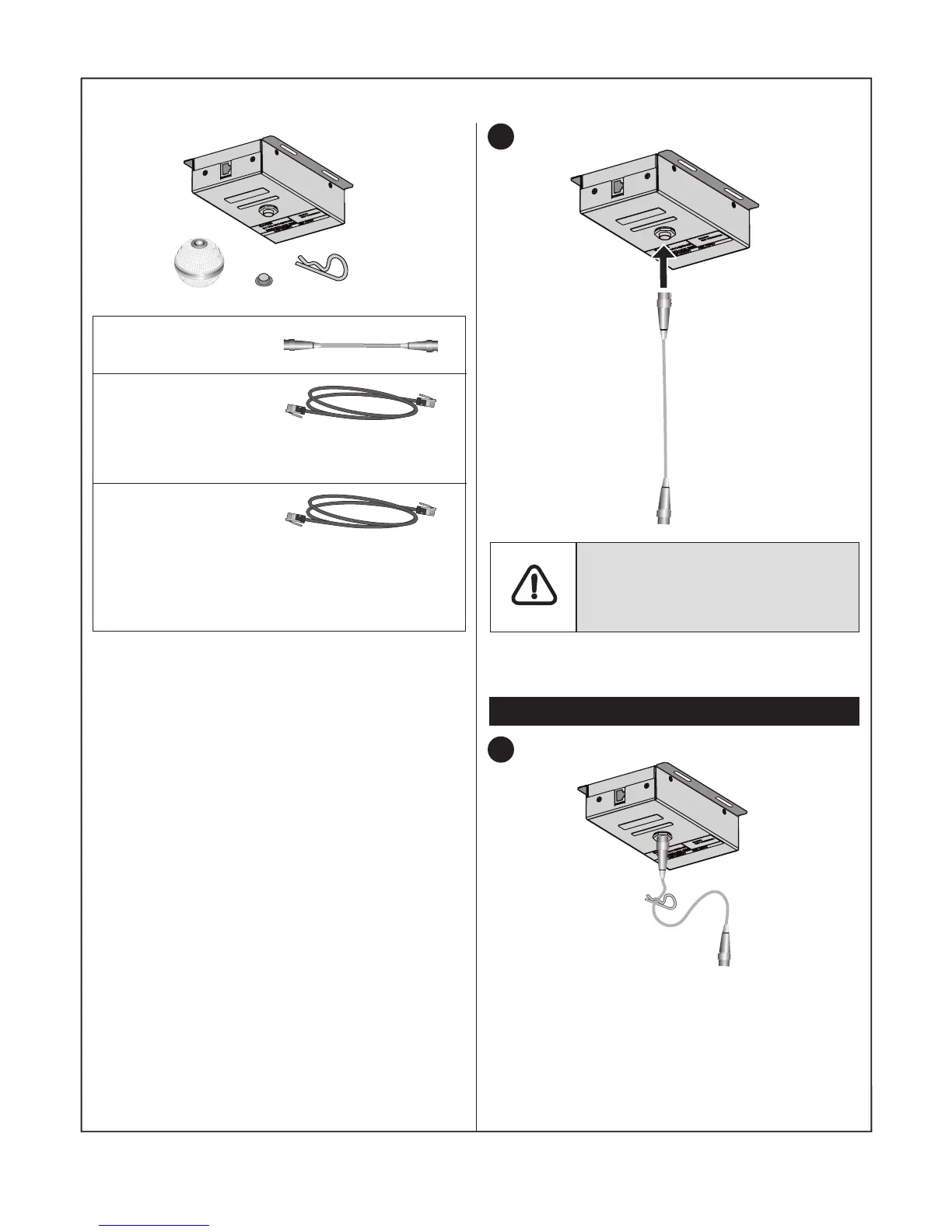
1
Verify that the number of pins on the
cable connector matches the number
of pins on the connector on the
electronics enclosure.
If you do not have a suspended ceiling in your
room, continue with Step 10 on page 10.
For suspended ceilings
2
If height adjustments are required for the
microphone ball, clip the cable clip onto the
cable. When you later place the electronics
enclosure on the ceiling tile, you can rest the
clip above the hole in the ceiling tile and adjust
the length of the cable as needed.