DESCRIPTION DESCRIPTION DESCRIPCIÓN
55 522‐5101 SEATVALVESUCTIONCHAMBER SIÈGEDELACHAMBRED'ASPIRATION ASIENTODELACÁMARADESUCCIÓN
55 522‐5102 SEATVALVEAIRCHAMBER SIÈGEDELACHAMBREÀAIR ASIENTODELACÁMARADEAIRE
56 522‐5105 WINDOW FENÊTRE VENTANILLA
57 522‐5303 RODWIPER CAOUTCHOUCD'ESSUYAGETIGEPISTON LIMPIADORDELVÁSTAGODELPISTÓN
58 522‐5305 HEADPISTONPIN GOUPILLEDELATÊTEDUPISTON PASADORDELACABEZADELPISTÓN
59 522‐5306 S‐275PISTONWASHER RONDELLEDUPISTONS‐275 RONDANADELPISTÓNS‐275
60 522‐5311 1/4"WASHER(PLATED) RONDELLEPLATE1/4"(PLAQUÉ) RONDANAPLANA1/4"(CHAPEADO)
61 522‐5312 1/4''WASHER(BRASS) RONDELLEENLAITON1/4'' RONDANADELATÓN1/4"
62 522‐5313 5/16"WASHER(PLATED) RONDELLEPLATE5/16"(PLAQUÉ) RONDANAPLANA5/16"(CHAPEADO)
63 522‐5800 S‐275WATERBOXASS'Y(13‐55‐35‐63) BOÎTEÀEAUMONTÉES‐275(13‐55‐35‐63) CAJADEAGUAMONTADAS‐275(13‐55‐35‐63)
64 522‐5500 S‐275PISTONCUPASS(19‐59‐44‐10‐29) PISTONASSEMBLÉS‐275(19‐59‐44‐10‐29) PISTÓNENSAMBLADOS‐275(19‐59‐44‐10‐29)
522‐2801 S‐275REPAIRKIT NÉCESSAIREDERÉPARATIONS‐275 ESTUCHEDEREPARACIONESS‐275
66 522‐3515 PACKINGBOXASS'Y(35‐33‐45‐32) PRESSE‐ÉTOUPEMONTÉ(35‐33‐45‐32) ENSAMBLEPRESIÓNMONTADO(35‐33‐45‐32)
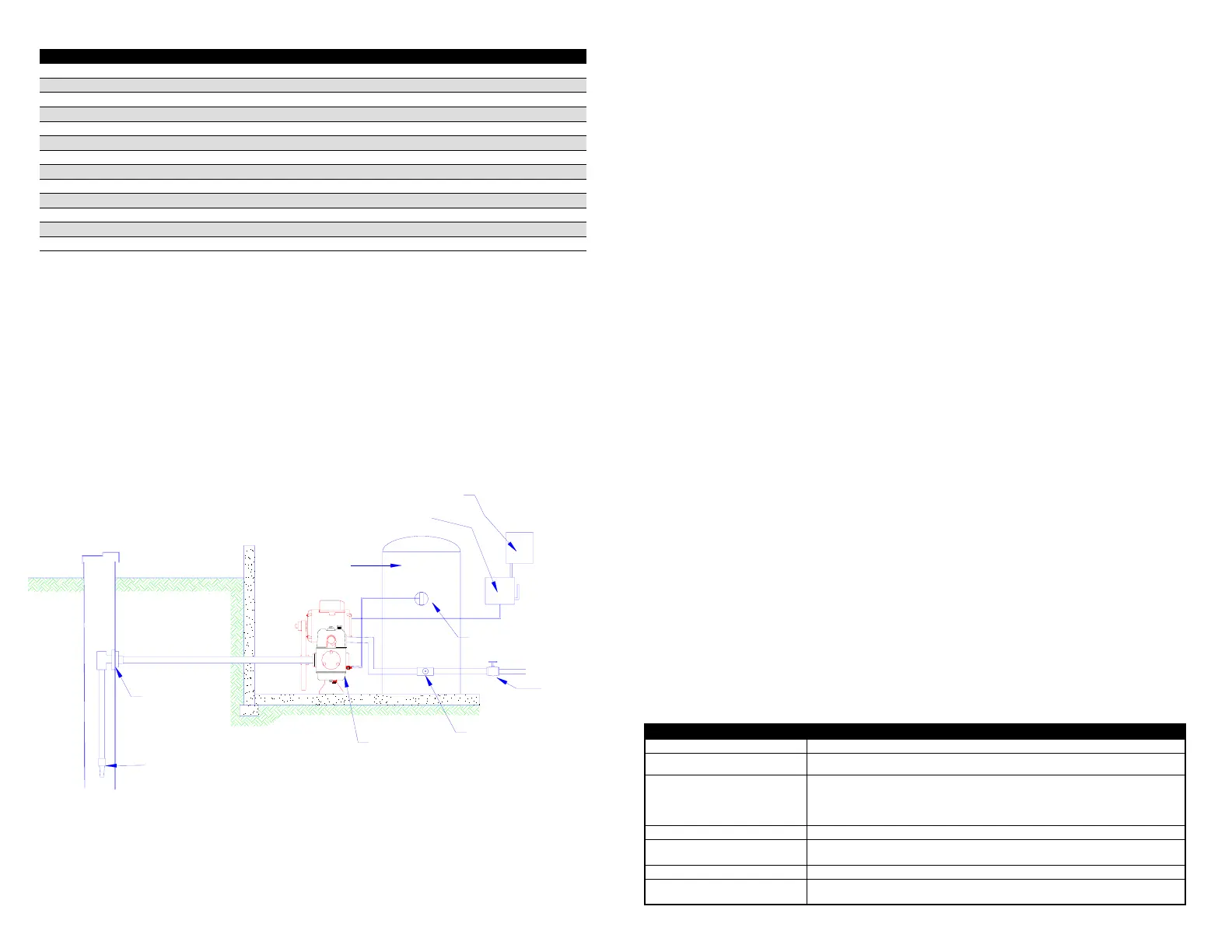
VALVE
SOUPAPE
VALVULA
ELECTRICAL DISCONNECT
SÉLECTIONNEUR ÉLECTRIQUE
SELECTOR ELÉCTRICO
AIR VOLUME CONTROL
CONTRÔLE DE VOLUME D'AIR
CONTROL DE VOULMEN DE AIRE
ELECTRICAL ENTRY
ENTRÉE ÉLECTRIQUE
ENTRADA ELÉCTRICA
TANK TEE
TÉ RÉSERVOIR
TEE PARA TANQUE
PISTON PUMP
POMPE À PISTON
BOMBA PISTONES
PITLESS ADAPTOR
COULISSEAU
CURSOR DE AJUSTE
FOOT VALVE
CLAPET DE PIEDS
VALVULA DE PIE
GALVANIZED TANK
RÉSERVOIR GALVANISÉ
TANQUE GALVANISADO
TYPICALPISTONPUMPINSTALLATION
INSTALLATIONTYPIQUED'UNEPOMPEÀPISTON
INSTALACIÓNTÍPICABOMBADEPISTONES
PISTON PUMP INSTALLATION INSTRUCTIONS
IMPORTANT: Read carefully this instruction manual before installing or operating the pump.
SECURITY - DANGER
Read with attention the security warning messages.
ATTENTION:
⇒ Read instructions before operating the pump.
⇒ The electrical installation must be in accordance with the Local guide of electricity and with all other
applicable local codes and rules.
WARNING - ELECTROCUTION RISK:
⇒ Call upon a qualified electrician for the motor’s electrical supply.
⇒ Make sure that the motor is correctly grounded and that all connections are safe and watertight.
⇒ Before proceeding with the maintenance of the pump, always shut down the motor’s electrical supply.
Start up
1) Unscrew the plug (#37) on the pump body and fill pump body with 7 ounces (200 ml) of SAE-
30 oil, filler hole location is indicated by arrow on the window.
2) Choose a location for your pump as close as possible to the water supply. It is
recommended to install a suction pipe of 1 ¼" (minimum). Piping should be arrange with
a gradual incline to the water source, without links.
3) Install foot valve assembly on the suction line, and place line into well below the water level.
Priming
• Remove the priming plug (#38) from the air chamber
• Fill water box
• Put the priming plug back in its place
• Start the pump.
The pump should be now in normal operation
Maintenance
1) Periodically check the oil level in the pump body.
2) Slightly tighten the packing retainer nut.
3) For replacement parts and repair kits contact your local dealer or the manufacturer if a dealer
is not available.
Winterizing
If your pump is not to be operated during winter, carefully follow the present instructions for
draining pump. You will then eliminate the possibilities of cracking the water box that could be
caused by freezing :
• Remove primer plug (#38)
• Remove drain plugs (#37) located under suction chamber
• Start and run pump for a few seconds to completely drain.
Suction and discharge lines should be removed for storage.
PROBLEMS TROUBLE SHOOTING
Motor rumbles but do not start. Check : a) Voltage b) Tension of packing box nut c) Tension on ‘’V’’ belt
Motor stops and starts too often Check: a) Not enough air in tank b) Air valve blocked.
Air is discharged with water.
Air/water ratio incorrect, too much air in tank or using of diaphragm tank.
Check : a) Air valve operation b) Leak in suction pipe or packing box
c) Water level lower than suction line, add pipe if 25 feet (7,62m) of vertical
line is not already used
Overheating motor. Check : a) Wiring b) ‘’V’’ belt tension
Pump does not maintain loaded
Check : a) Foot valve b) Piping c) Water level in well d) Dirt under
rubber valve
No water in tank. Check: a) Leak b) the water level it must always be above the foot valve.
Low pressure.
Check : a) Piston leather b) Dirt under rubber valve
Replace parts if necessary.
 Loading...