SWC Cell Cable Connection
Installing the pH Control System
Units with pH control have an injection fitting and a peristaltic pump which must be
installed. Refer to the installation diagram on the next page for details.
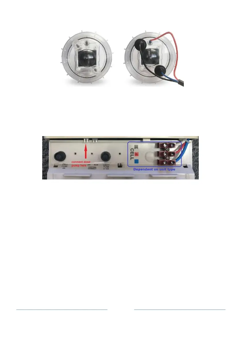
Position the dosing pump as indicated in the installation diagram, ensuring it is NOT too
close to other equipment or power outlets (due to corrosive fumes from the acid). Attach
the dosing pump to the wall and connect it to the power supply where indicated in the
photograph below.
Fit the injection point, avoiding high pressure areas (ie not between pump and filter). It can
go prior to the cell if necessary.
Cut a length of tubing that will reach from the base of the peristaltic pump to the injection
fitting. Connect one end of the tubing to the outlet side of the peristaltic pump (the
direction of flow is indicated by an arrow on the front cover of the pump.) Connect the
other end of the tube to the injection point.
Cut another length of tubing that will reach from the base of the peristaltic pump to the
base of the acid drum. Position the acid drum in a safe and secure location, preferably
about 2 metres from the Power Supply Unit
Connect the one end of this tube to the inlet side of the peristaltic pump (the direction of
flow is indicated by an arrow on the front cover of the peristaltic pump.)
Drill an 8mm hole in the lid of the acid drum and pass the tubing through the hole in the
drum lid. Place a sinker on to the end of the tubing that will be in the drum and then attach
the drum filter. Note that the drum filter incorporates a non-return valve to prevent back-
flow into the chemical drum. Lower the drum filter and sinker into the drum and screw on
the lid.