GETTING STARTED
Page 11
GETTING STARTED
STABILISERS POSITIONIN G
Stabilisers are supplied and must be used for all MI TOWER heights.
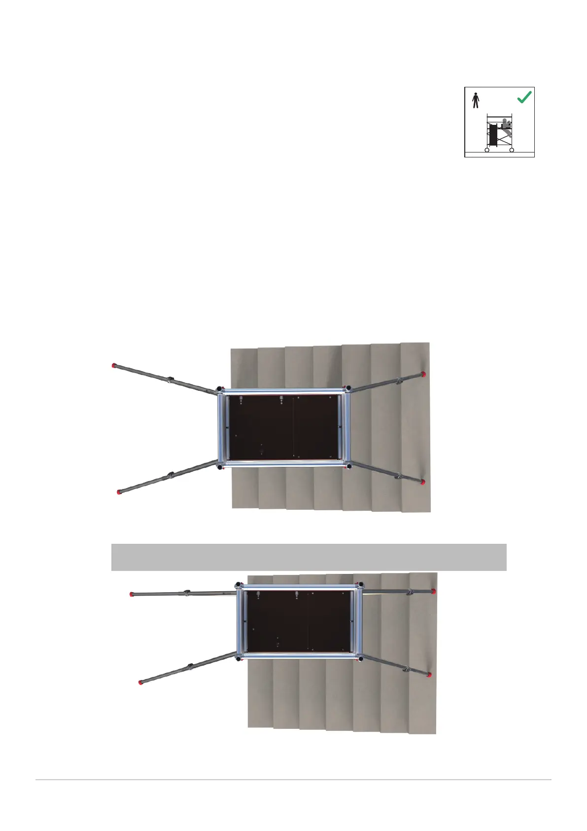
For maximum effect arrange the stabilisers by positioning at an angle of 45 degrees to give a footprint as close
to square as possible as shown in fig.1.
but only where the heights of the wall is a minimum of two thirds the height of the top working platform.
Ensure that all four stabilisers’ feet are in contact with the ground and that the ground can support the weight
of the tower and stabilisers.
MIN.
1
MI TOWER requires only one person to assemble and dismantle it. Your MI TOWER is
supplied with uniform 1m high rung frames which can be used at any stage of the assembly.
During erection, the frames may be connected together to create 2m high frames which
makes assembly both quicker and easier.
Fig. 2
Wall
If the tower is to be positioned against a wall, the stabiliser footprint can be altered as shown in fig 2
Fig. 1
 Loading...