This document describes the installation and features of the PORT GUARD Deadbolt Lock.
Function Description:
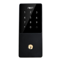
The PORT GUARD Deadbolt Lock is a smart deadbolt designed for residential use, offering multiple methods of access including a keypad, manual key, and potentially a fob reader (indicated by "Keypad & Fob Reader" in the product overview). It is a deadbolt lock, meaning it provides an additional layer of security beyond a standard doorknob lock. The lock is designed for easy installation, requiring only a Phillips head screwdriver and no drilling. It features a battery-powered operation with a USB port for potential emergency power or data transfer, and a reset button for system resets. The lock's direction (left-hand or right-hand opening) is adjustable after installation via a specific keypad sequence, ensuring compatibility with various door configurations.
Important Technical Specifications:
- Backset Adjustment: The latch is adjustable for backsets of 60mm (2-3/8 inches) and 70mm (2-3/8 inches), accommodating different door preparations.
- Power Source: The lock is battery-operated, requiring four batteries (type not specified, but typically AA or AAA for similar devices).
- Connectivity: While not explicitly detailed, the "Keypad & Fob Reader" suggests support for RFID fobs in addition to keypad codes. The presence of a USB port could indicate capabilities for firmware updates, emergency power, or data logging.
- Components: The system includes an exterior assembly (keypad and fob reader), an interior assembly (battery pack, knob, and circuit board), a bolt and strike plate, and various screws for installation.
Usage Features:
- Keypad Access: Users can enter a numerical code on the front panel keypad to unlock the deadbolt. The keypad features standard numbers 0-9, an asterisk (*), and a pound sign (#).
- Manual Key Override: A traditional manual key is provided for mechanical unlocking, serving as a backup in case of battery failure or electronic malfunction. The keyhole is located on the exterior assembly.
- Fob Reader: The "Keypad & Fob Reader" suggests the ability to unlock the door using compatible RFID fobs, offering a convenient, keyless entry option.
- Adjustable Lock Direction: The lock's orientation can be configured for either left-hand or right-hand opening doors using a specific keypad sequence (*46#123456#1 for left-hand, *46#123456#2 for right-hand), ensuring proper operation regardless of door swing.
- Vertical Knob Orientation: During installation, it is crucial that the interior knob is in a vertical position to ensure correct functionality.
Maintenance Features:
- Battery Replacement: The interior assembly includes a removable battery cover, allowing for easy replacement of the four batteries when needed.
- Reset Button: A reset button is located on the interior assembly, likely used for factory resets or troubleshooting.
- Simple Installation: The manual emphasizes "No drill needed" and provides clear, step-by-step instructions with diagrams, making installation straightforward for users. The process involves adjusting the backset, installing the bolt, mounting the front and back panels, connecting the wire connector, and inserting batteries.
- Troubleshooting Support: The manual provides contact information for Port Security System LLC, including a phone number (800-219-2366) and email (Authority@portsmartlock.com), for technical questions or support. A website (www.portsmartlock.com) is also provided for further resources.