10
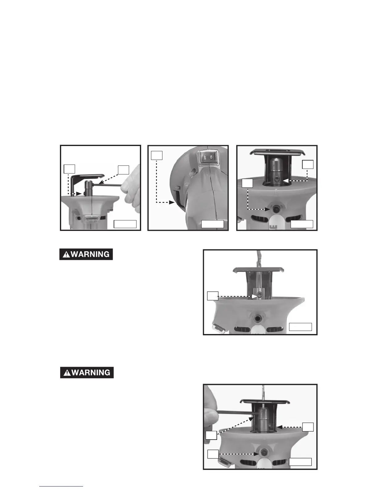
A
B
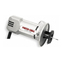
Fig. 3
A
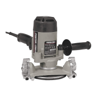
Fig. 4
A
B
INSTALLING A BIT WITH 1/4" SHANK
Be sure the power
switc h is in the
"OFF" position and that the tool is
disconnected from the power source
to avoid accidental starting which
could result in personal injury.
1. Clean and insert a bit shank into the
Cutout Tool spindle (Fig. 6). The bit
shank must extend at least 1/2" into
the spindle.
2. Engage the spindle lock (B) Fig. 5.
3. Firmly tighten the screw (A) Fig. 6.
INSTALLING A BIT WITH .115" OR 1.8" SHANK
Be sure the power switch is in the "OFF" position and that
the tool is disconnected from the power source to avoid
accidental starting which could result
in personal injury.
1. Clean and insert the shank of the
special chuck into the spindle until it
bottoms (Fig. 7)
NOTE:
To minimize vibration levels, insert
the special chuck with setscrew (B) Fig. 7
180º from the shaft set screw (A).
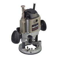
Fig. 5
A
Fig. 6
B
A
Fig. 7
C
Use the special chuck supplied with the 7499 to install bits with either .115" or
1/8" shanks. Insert the special chuck directly into the spindle shaft of the Cutout
Tool and secure it with the screw (A) Fig. 3. Insert the bit shank into the special
chuck and secure it with the screw (B) Fig. 3.
NOTE: To minimize vibration levels, insert the special chuck with set screw (B)
Fig. 3, 180 degrees from the shaft setscrew (A).
Use the hex wrench (A) Fig. 4 (stored in the tool housing) to tighten or loosen the
bit retaining screws. Use your thumb to rotate the hex wrench clockwise, away
from the tool housing. Grasp the wrench to pull it from the storage pocket.
The Cutout Tool is equipped with a spindle lock to prevent the spindle from
rotating when you install or remove bits. To engage the spindle lock, first rotate
the spindle shaft (by hand) to position the screw (A) Fig. 5 in line with the spindle
lock button (B). Depress and hold the spindle lock button. Rock the spindle
back and forth (by hand) to ensure that the lock is engaged.