10
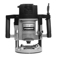
1. Open the clamp (A) Fig. 1 and set the power unit in the base unit.
2. Align the rack and pin (C) Fig. 1 of the power unit with the grooves in the
base. Pull the lever (B) Fig. 1, and lower the motor into the base.
3. Close the clamp (A).
4. Reverse the procedure to remove.
Applications using a templet guide
require the bit to be centered in the
guide. This, in turn, requires the
center hole in the sub-base to be in
line with the collet of the motor unit.
Your model has an adjustable sub-
base that has been aligned at the
factory. The fixed-base router
comes with the large hole (Fig. 4).
1. Open the clamp (A) Fig. 3.
2. Pull the lever (B) and set the router
on the workpiece. With the router
flat and level, let the bit barely
touch the workpiece.
3. Hold the lever (B) and turn the
depth knob (C) until the zero
aligns with the zero mark on the
router base.
4. Release the lever (B). Make sure
that the zero remains aligned with the zero mark.
5. Turn the knob (C) clockwise to the desired depth of cut.
6. Close the clamp (A).
NOTE: Setting the index line to 1/16" on the knob indicates that the cutting edge of
the bit is exposed 1/16" below the base.
Disconnect the tool from the power source!
ADJUSTING THE DEPTH OF CUT
A
C
B
Fig. 3
Fig. 4
C
B
D
A
INSTALLING THE MOTOR
Disconnect the tool from the power source!
ADJUSTING THE SUB-BASE ALIGNMENT (All Routers)
Disconnect the tool from the power source!