13
1. Lock the plunge locking lever (A) Fig.
10 by moving it to your right as far as
it will go.
2. Push in on the plunge locking lever
(A) Fig. 10.
3. Move the plunge locking lever (A) Fig.
10 to the desired location and allow it
to spring back into position.
NOTE: Pushing the plunge locking lever
down past the last stop will place the
router in the “free-plunge” mode.
ADJUSTING THE PLUNGE LOCKING LEVER
The plunge locking mechanism may be adjusted to compensate for wear, or to
reposition lever (in locked position). To adjust:
Disconnect the tool from the power source!
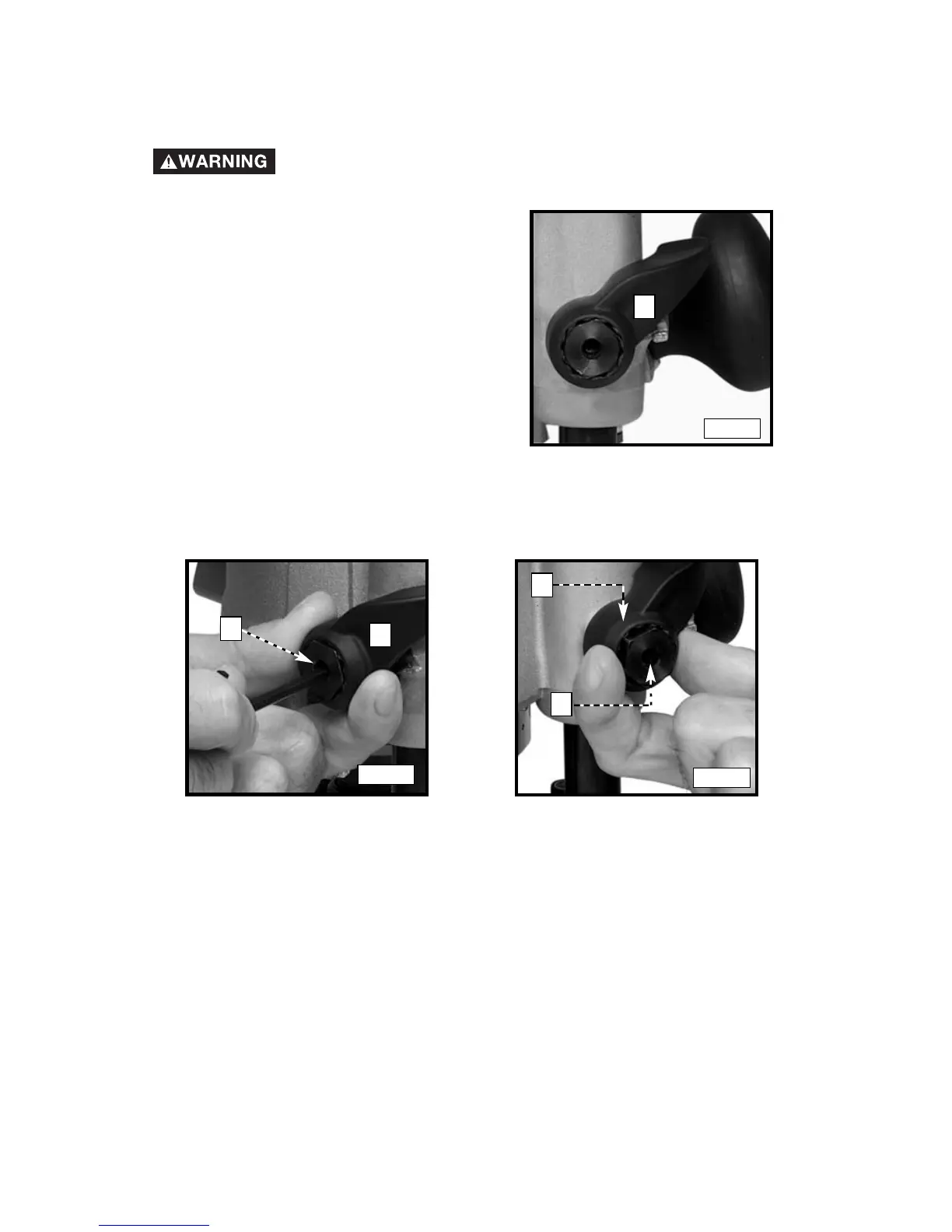
Fig. 10
A
To adjust the plunge locking mechanism:
Fig. 11
Fig. 12
B
A
A
B
1. Hold the plunge locking lever (A) Fig. 11.
2. Insert an 1/8" hex wrench (not furnished) through the center of the plunge-
locking bolt (B) Fig. 11 and into the adjustment screw. Turn the screw counter-
clockwise approximately one turn.
3. Push in on the plunge locking lever (A) Fig. 12 to expose the head of the
plunge-locking bolt (B) Fig. 12.
4. Hold the plunge-locking lever (A) Fig. 12 in. Turn the plunge-locking bolt
(B) Fig. 12 clockwise to cause the plunge-locking bolt to move in or
counter-clockwise to cause the plunge-locking bolt to move out. Turn it
one position at a time until you achieve the correct adjustment.