12
2. Release the plunge mechanism by pulling the locking lever (A) Fig. 10
down. Lower the plunge mechanism until the router bit touches the work
surface. Release the lever and push it to the right to lock the mechanism
in this position.
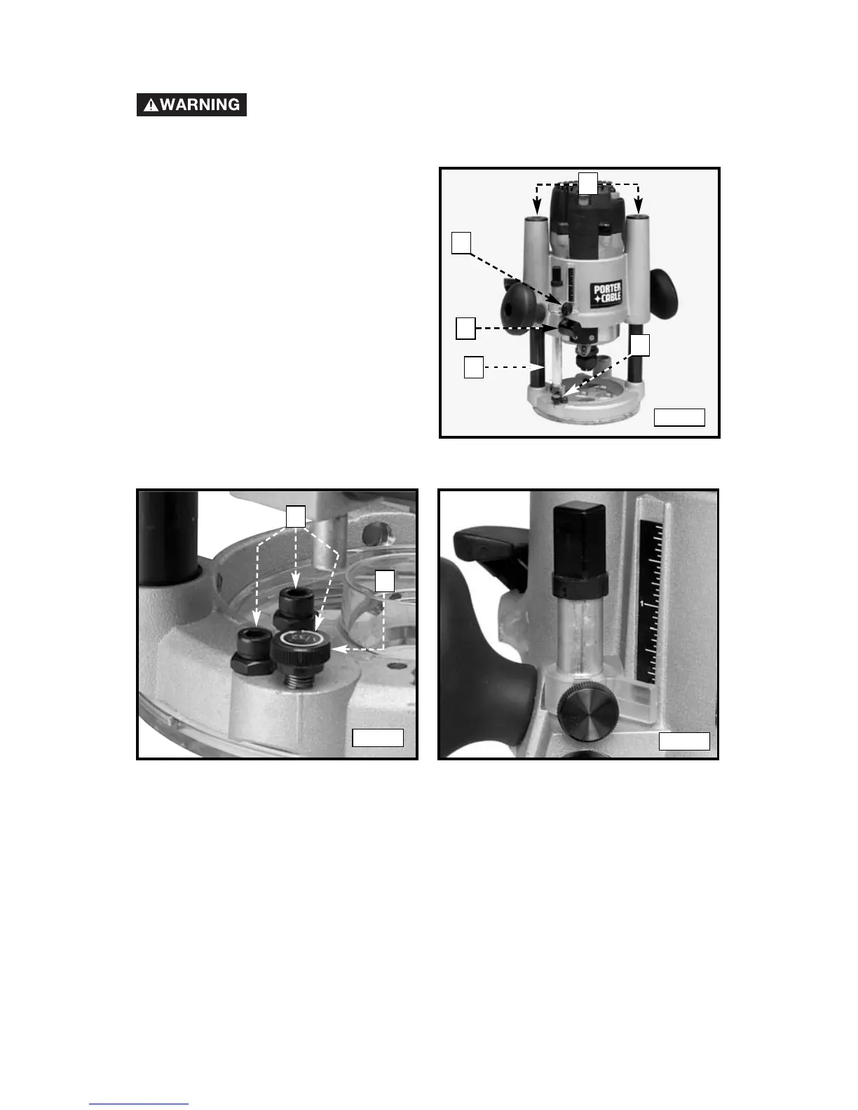
3. Tighten the depth-rod locking knob (A) Fig. 7.
4. Position the depth indicator (C) Fig. 10 at the “0” position and tighten the
knob (C) Fig. 7.
5. Loosen the depth-rod locking knob (A) Fig 7, and raise until the indicator
aligns with the graduation representing the desired depth of plunge (Fig.
9).
Fig. 8
Fig. 9
1. Loosen the depth rod locking
knob (A) Fig. 7, and depth
indicator knob (C) Fig. 7,
allowing the depth rod (D) Fig. 7
to contact one of the turret stops
(A) Fig. 8. Normally the deepest
desired cut is set with the depth
rod resting on the base casting
(B) Fig. 7. The other three
adjustable stops (A) Fig. 8 may be
adjusted to any desired height.
Any combination of fixed and/or
adjustable stops may be utilized
to achieve the desired depths
required for a particular job. The
adjustable stop (B) Fig. 8 will
raise or lower that stop by 1/32"
with one full turn of the stop.
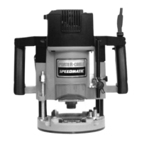
ADJUSTING THE PLUNGE BASE
Disconnect the tool from the power source!
Fig. 7
D
A
C
A
B
B
E