DESCRIPTION OF OPERATION
Drain Valve (A)Fig. 1: The drain valveis locatedat the base of
the air tank and is used to drain condensationat the end of
each use.
Motor Thermal Overload Protector (not shown)= The
electric motorhas an automaticthermal overloadprotector. If
the motor overheats for any reason, the thermal overload
\
protector willshut off the motor. The motor must be allowed to A
cool before restarting.
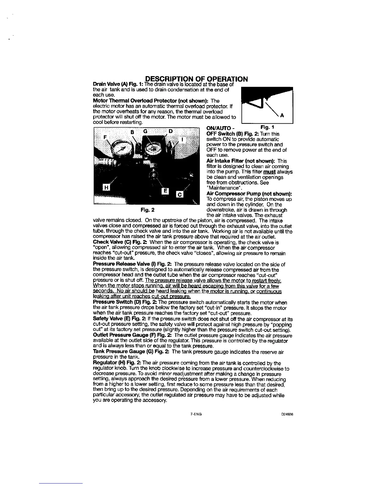
ON/AUTO- Fig. 1
B G D OFF Switch (B) Fig. 2: Turnthis
switchON to provide automatic
power to the pressureswitchand
OFF to remove power at the end of
each use.
Air Intake Rlter (not shown): This
filter is designed to clean air coming
into the pump. This filter must always
be clean and ventilation openings
freefrom obstructions. See
"Maintenance".
Air Compressor Pump (not shown):
Tocompress air,the pistonmovesup
and down inthe cylinder. On the
Fig. 2 downstroke, air isdrawn in through
the air intakevalves.The exhaust
valve remainsclosed. On the upstrokeof the piston,air iscompressed. The intake
valves close and compressedairis forced out throughthe exhaustvalve, intothe outlet
tube, throughthe check valveand intothe airtank. Workingair isnot available untilthe
compressorhas mieed the airtank pressureabove thatrequiredat the air outlet.
Check Valve (C) Fig. 2:. Whenthe air compressoris operating,the check valve is
"open", allowing compressedair to enter the airtank. When the aircompressor
reaches"cut-out" pressure,the checkvalve "closes", aUowingair pressure to remain
insidethe air tank.
P_ssure Release Valve (I) Rg. 2: The pressurerelease valvelocatedon the sideof
the pressure switch, isdesignedto automaticallyreleasecompressedairfromthe
compressorhead and the outtettube whenthe aircompressorreaches"cut-out"
pressureor isshutoft. The oreasuro release valveallowsthe motorto restartfreely.
When the motor etODSrunnino,air willbe heard eecaDino fromthisvalvefor a few
seconds. No airshouldbe heardleekinewhen the motoris runnino,or continuous
leekinoafter unit reachescut-out Dressure.
Pressure Switch (D) Fig. 2: The pressureswitchautomaticallystartsthe motorwhen
the airtank pressuredropsbelowthe factoryset "cut-in" pressure. Itstops the motor
when the airtank pressure reachesthe factoryset "cut-out" pressure.
Safety Valve (E) Fig. 2: Ifthe pressureswitchdoes not shutoffthe aircompressorat its
cut-out pressure setting,the safetyvalvewillprotectagainsthighpressure by "popping
out"at its factoryset pressure (slightS/higherthan the pressureswitchcat-out setting).
Outlet Pressure Gauge (P)Fig. 2: The outlet pressure gauge indicatesthe air pressure
availableat the outletsideof the regulator. This pressureis controlledby the regulator
and is alwaysless thanor equalto the tank pressure.
Tank Pressure Gauge (G) Fig. 2: The tank pressuregauge indicatesthe reserve air
pressureinthe tank.
Regulator (H) Fig. 2: The airpressurecoming fromthe airtank iscontrolled by the
regulatorknob. Turnthe knobclockwiseto increasepressureand counterclockwiseto
decrease pressure.To avoidminorreadjustmentafter makinga change inpressure
setting, alwaysapproach the desiredpressure from a lower pressure. When reducing
from a higher to a lower setting,first reduceto some pressureless than thatdesired,
then bring up to the desiredpressure.Depending on the air requirementsof each
particularaccessory,the outletregulatedair pressuremay have to be adjustedwhile
you are operatingthe accessory.
7-ENG D24938