
H
Haley ChenJul 31, 2025
What to do if Portwell Motherboard won't power on?
- EErica YoungJul 31, 2025
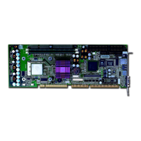
If your Portwell Motherboard system doesn't power on, start by verifying the ROBO-8712VLA jumper, JP3. For an AT power supply or an ATX power supply used for an AT system, ensure JP3 is set to 1-3 and 2-4. Otherwise, it should be at 3-5 and 4-6. Also, double-check that every connector is securely attached with the correct cable. If you've changed the processor with a different system clock, clear the CMOS by moving JP1 to 2-3, power on the system, power off, return JP1 to 1-2, and then power on again.