This document outlines the operating and maintenance procedures for the BAUER KOMPRESSOREN PE 250-MVE and PE 300-MVE high-pressure compressors, designed for breathing air applications.
Function Description
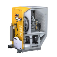
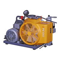
The compressor units serve as stationary filling stations for compressing breathing air in the high-pressure range, primarily for filling diving or breathing protection bottles. They are not intended for continuous industrial application.
The core functions of the unit include:
- Suction: The medium (air or gas mixture) is drawn into the compressor via the suction section.
- Compression: The compressor block compresses the medium to its final pressure. During this process, the medium is pre-cleaned using a separator and cooled by heat exchangers.
- Filtration: A filter system performs the final cleaning of the compressed gas mixture.
- Distribution: Filling fittings are used to distribute the prepared gas mixture, connecting consumers to the compressor unit via special valves and filling couplings.
- Drive: An electric motor drives the compressor using a V-belt.
- Water Removal: An automatic condensate drain regularly empties the separators, directing accumulated water and oil condensate into a collection vessel.
- Control Unit: An electric control system monitors and manages the compressor unit's operation.
Important Technical Specifications
The manual details specifications for two models: PE 250-MVE and PE 300-MVE.
General Performance Characteristics:
- Medium: Air
- Suction pressure: Atmospheric
- Operating pressure max.: 350 bar
- Blow-off pressure, final pressure safety valve: 225 / 330 bar
- Switch-off pressure: 220 / 320 bar
- Setting pressure, pressure retention/non-return valve: 160 bar
- Setting times of automatic condensate drain (interval / duration): 15 min / 6 s
- Compressor block: IK120
- Drive motor type: E-motor (three phase AC)
- Maximum permissible inclination of the compressor: 5°
- Noise pressure level: 77 dB(A)
Model-Specific Data:
PE 250-MVE:
- Delivery volume (10 l cylinder filling from 0 to 200 bar, ± 5%): 250 l/min
- Cooling air flow, min.: 1980 m³/h
- Speed: 1450 rpm
- Motor power: 5.5 kW
- Dimensions: 1050 x 755 x 1315 mm
- Weight: 250 kg
- Standard operating voltage: 400 V
- Standard frequency: 50 Hz
PE 300-MVE:
- Delivery volume (10 l cylinder filling from 0 to 200 bar, ± 5%): 300 l/min
- Cooling air flow, min.: 2700 m³/h
- Speed: 1800 rpm
- Motor power: 7.5 kW
- Dimensions: 1050 x 755 x 1315 mm
- Weight: 260 kg
- Standard operating voltage: 400 V
- Standard frequency: 50 Hz
Compressor Block IK120 Data:
- Number of stages: 3
- Number of cylinders: 3
- Cylinder bore (1st, 2nd, 3rd stage): 88 mm, 36 mm, 14 mm
- Piston stroke: 40 mm
- Direction of rotation (looking onto flywheel): Left
- Drive type: V-belt
- Blow-off pressure of safety valve (1st, 2nd stage): 9.9 bar, 60 bar
- Oil quantity: 2.8 l
- Oil pressure: 4.5 ±1.5 bar
- Intake pressure / inlet pressure: 0 (atmospheric) bar
Filter System P31 Data:
- Operating pressure max.: 350 bar
- Pressure dew-point: <-20 °C (corresponding to 3 mg/m³ at 300 bar)
- Pipe connections: G 3/8" (condensate drain G 1/4")
- Filter content: 1.3 l
- Classification as per Pressure Equipment Guideline: Vessel category II
- Processable air volume (referred to 20 °C and 300 bar): 615 m³
- Note: If a cartridge with CO removal is used, processable air volume reduces by approx. 26%.
Filter System P41 Data:
- Number of cartridge filters: 1
- Operating pressure max.: 350 / 420 / 550 bar
- Operating pressure min.: 90 bar
- Deployment temperature range: +5 ... +50 °C
- Residual water content max.: 10 mg/m³
- Residual oil content max.: 0.1 mg/m³
- Residual carbon monoxide (CO) content max.:* 5 mg/m³ (*Only with CO removal cartridges and max. 25 ml/m³ CO in intake air)
- Max. permissible number of load cycles: See accompanying pressure equipment operating instructions.
Ambient Conditions:
- Maximum permissible ambient temperature: +5 ... +45 °C
- Location: 0 ... 1500 m above sea level
- Explosion protection: No
Usage Features
The compressor units offer both semi-automatic and fully automatic operating modes.
Operating Modes:
- Semi-automatic: The compressor starts manually and switches off automatically upon reaching the set switch-off pressure. Manual restart is required. It can be switched off manually at any time.
- Fully automatic: The compressor starts manually, then operates based on pressure. It switches off automatically at the switch-off pressure and restarts automatically when the switch-on pressure is reached. This cycle continues until manually switched off.
Display Elements:
- Phase sequence monitor: Indicates the correct phase sequence.
- Oil level gauge: Shows the current oil level.
- Pressure gauge (filter system): Displays pressure within the filter system (P42 only).
- SECURUS monitoring device (optional): Provides filter saturation monitoring with LED indicators for cartridge condition (OK, almost exhausted, exhausted, missing/interrupted) and unit condition (in operation, switch-off).
- B-TIMER (optional): Displays maintenance due, low battery status, operating hours/cartridge number, and cartridge saturation. It has selection and input keys for navigation and settings.
Operation with B-TIMER:
- The B-TIMER activates with compressor operation, indicated by a flashing "h". It can also be switched on manually by pressing any button.
- The display toggles between main menu, remaining filter capacity, operating hours until service intervals (A, B, C), and flashing filter cartridge number.
- Resetting: Filter capacity and maintenance intervals can be reset after cartridge replacement or maintenance by switching to the relevant display and pressing the input key for >5 seconds.
- Setting values: Filter cartridge number, delivery volume, operating pressure, and operating hours can be configured in the setup menu.
Filling Operation:
- Safety: Emphasizes the danger of poisoning from pollutants in breathing air, requiring air intake to be free from toxic gases, exhaust, or solvent vapours. Breathing air cylinders should not be filled with air from workrooms or if CO content exceeds 25 ppmV.
- Purging: After a standstill of more than 6 hours, the compressor unit must be purged for 2 minutes with open outlet/venting valve to release bound CO2 from the filter cartridge.
- Cylinder Connection: Compressed air cylinders with international filling connections can be connected using the international bracket filler connection.
- Filling Process: Connect the cylinder, open the filling cock, allow the cylinder to fill, close the cylinder cock and filling cock, then remove the cylinder.
- Cooling: Cylinders heat up during filling; allow them to cool before re-connecting for further filling to achieve nominal working pressure.
- Safety Valve: The final pressure safety valve is not designed for continuous operation; the unit should be shut off once filling pressure is reached.
Maintenance Features
The manual provides detailed instructions for various maintenance activities, emphasizing the importance of regular checks and the use of a service log book for warranty claims.
General Maintenance Principles:
- Personnel: Only trained, instructed, or competent personnel should operate and maintain the machine. Service and installation activities must be carried out by personnel trained and authorized by BAUER KOMPRESSOREN.
- Safety: Always follow safety instructions, wear personal protective equipment (hearing protection, goggles), and ensure the unit is de-energized and secured before maintenance.
- Original Parts: Only original spare parts and approved operating supplies (oils, cleaning agents) should be used.
- Documentation: Keep the instruction manual handy, and record all maintenance activities in the service log book.
Key Maintenance Activities:
-
Lubricating Oil System:
- Checking Oil Level: Regularly check the oil level using the oil level gauge; it must be between the minimum and maximum marks. Refill if necessary.
- Oil Change: Replace the oil after an extended period of storage or every 2 years. The oil filter must be replaced after each oil change. Used oil must be disposed of as special waste.
- Changing Oil Type: Follow specific instructions to avoid damage, including checking and cleaning valves, coolers, separators, and lines for deposits.
- Venting Oil Pump: If oil pressure doesn't build up after starting, the oil pump may need venting, especially after maintenance or incorrect rotation direction.
-
Intake Section:
- Replacing Suction Filter: Maintenance intervals depend on air dustiness. Remove, brush/blow out, or replace the filter element. Clean the housing with a damp cloth.
-
Filter System:
- Changing Cartridge: Replace the cartridge after reaching maximum operating hours. De-pressurize the unit, remove the filter head using a special tool, extract the old cartridge, clean the housing, insert a new cartridge (removing protective caps), lubricate fittings, and screw the filter head back in. Dispose of saturated cartridges as special waste.
-
Pressure Retention Valve:
- Checking Function: Check for leak-tightness and proper functioning. The opening pressure can be observed on the pressure gauge.
- Adjusting: Only trained personnel should adjust the valve. Disengage locknuts, unscrew the setting screw, and re-adjust the opening pressure. Rotation to the right increases pressure, to the left reduces it.
-
Filling Equipment:
- Maintaining Filling Valves: The sintered filter in the filling valve body should be cleaned or replaced if contaminated. This involves de-pressurizing the unit, unscrewing the pressure gauge, removing the sintered filter, cleaning it, and reassembling.
-
Safety Valves:
- Checking Function: The blow-off pressure of safety valves must be checked at regular intervals (annually recommended). The final pressure safety valve can be vented to check its function, but the test pressure should be restricted to 80% of the final pressure. If it doesn't blow off, replace it.
- Blow-off Pressure Check: Compare the blow-off pressure with the final pressure display. Intermediate pressure safety valves are difficult to test and should be replaced carefully.
-
Pressure Gauge:
- Maintenance: Pressure gauges must be checked according to the maintenance schedule, preferably using a special testing pressure gauge. Replace if large inaccuracies are observed.
-
Intake Valves and Pressure Valves:
- Servicing: Clean contaminated valves with diesel oil or petroleum and a soft brush. Check parts for wear and replace if necessary. Clean valve chambers. Reassemble, checking seals and O-rings. Tighten valve head screws with a torque wrench.
- Replacing: Only competent personnel should replace valves, always in sets.
-
Automatic Condensate Drain:
- Checking Function: After a water removal operation, open condensate drain cocks of individual filters. If little condensate emerges, it's working properly. If a lot emerges, find and eliminate the fault. Clean the float switch in 40-litre condensate vessels to prevent sticking.
- Adjusting Timer: Only competent personnel should set the timer for condensate drain intervals. This involves accessing DIP switches and potentiometers to set drain interval and duration.
-
Electrical System:
- Maintenance: Check all screwed terminal connections in the switchgear box for tightness, especially on power contactors. Required safety checks (BGV, DIN VDE) must be performed.
- Adjusting Final Pressure Switch: Only competent personnel should adjust this. Use a 6-mm hexagon socket wrench to set the required pressure.
- Replacing B-TIMER Battery: A weak battery is indicated by a symbol. Unscrew the housing, pull out the plug, replace the battery, reconnect the plug, and close the housing. Data is saved during replacement.
-
Drive System:
- Electric Motor Maintenance: Clean the exterior occasionally and follow the motor manufacturer's specific maintenance instructions.
- V-belt Maintenance: Check the V-belt for damage and wear. This requires removing the V-belt guard. Replace damaged/worn V-belts in sets, lifting the motor slightly to place new belts.
Decommissioning and Disposal:
- Decommissioning: Disconnect from power, depressurize, disconnect pneumatic connections, drain and collect condensate and oil, and remove filter cartridges.
- Disposal: Dispose of the unit, dismantled components, and collected substances (electrical waste, electronic components, lubricants, chemicals, plastic, cardboard, paper, metallic components) according to local regulations and by licensed specialized companies.