Do you have a question about the POSIFLEX KS-6910 and is the answer not in the manual?
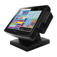
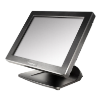
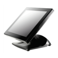
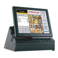
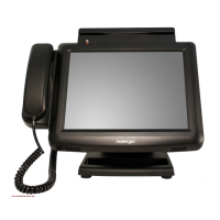
Provides a summary of the KS series POS terminals and their applications.
Details the system hardware specifications including CPU, Memory, and Storage.
Details the DC power adapter specifications and power consumption.
Explains the function and location of LED indicators for different models.
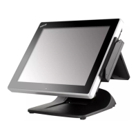
Describes the touchscreen panel type, input mode, and durability.
Details screen size, resolution, memory, and color depth.
Provides dimensions and net weight for different models.
Details Ethernet LAN port speed and Wi-Fi standards.
Specifies temperature and humidity ranges for operation and storage.
Lists system and power supply compliance and certification standards.
Specifies the durability of the resistive touchscreen in terms of touches.
Specifies the durability of the Magnetic Stripe Reader (MSR) in terms of passes.
Provides the Mean Time Between Failure (MTBF) for the system.
Illustrates the system's internal component connections and data flow.
Defines the pinout for the 12V DC input connector.
Details the pinout configuration for the LAN port.
Defines the pinout configuration for USB ports (USB0-USB3).
Defines the pinout configuration for the Cash Drawer (CR) port.
Details the pinout and configuration for Serial Ports Com1 and Com2.
Details the pinout and configuration for Serial Port Com3.
Defines the pinout for the SATA HDD connector.
Defines the pinout for the HDD power connector.
Details the default IRQ assignments for system ports and how to change them.
Describes the KP-450 45-key programmable keyboard accessory.
Details specifications for the Magnetic Stripe Reader accessory.
Details specifications for the Optical Fingerprint Sensor accessory.
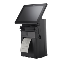
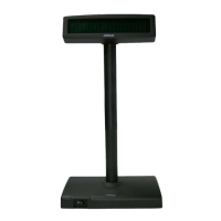
Details specifications for the Customer Display accessory.
Provides installation instructions for the WB-6812 Wall Mount Kit.
Explains how to configure system power on/off behavior via BIOS.
Steps to access the system's BIOS setup utility.
Configures the system to wake up upon receiving a modem ring signal.
Configures the system to wake up at a scheduled time.
Defines system behavior after an accidental power loss.
Covers issues related to HDD, SSD, and CF card configurations.
Manages touch screen settings and provides access to other touch tools.
Procedure for calibrating touch point accuracy on the screen.
Adjusts cursor behavior near screen edges for easier touch interaction.
Enables screen touch to function as a right-click.
Commands to write data to the microcontroller for hot key control.
Commands sent from MCU when hot keys are pressed.
Step-by-step guide for replacing the Hard Disk Drive or Solid State Drive.
Step-by-step guide for replacing the system's main board.
Diagram and labels for components on the top side of the main board.
Diagram and labels for components on the bottom side of the main board.
Details the function and behavior of various jumpers on the main board.
Defines the purpose and name of each header and connector on the main board.
Lists part numbers and descriptions for the KS-6910 model.
Lists part numbers and descriptions for the KS-6910TS model.
Visual representation of the KS-6910 parts and their assembly.
Visual representation of the KS-6910TS parts and their assembly.
| Storage | 64GB SSD |
|---|---|
| Weight | 1.8 kg |
| Type | Touch terminals |
| Processor | Intel Celeron J1900 |
| Operating System | Windows 10 IoT Enterprise |
| Touch Technology | Projected Capacitive |
| LAN Port | 1 x RJ-45 |
| Dimensions | 252 mm x 178 mm x 215 mm |