Pic.3
A B
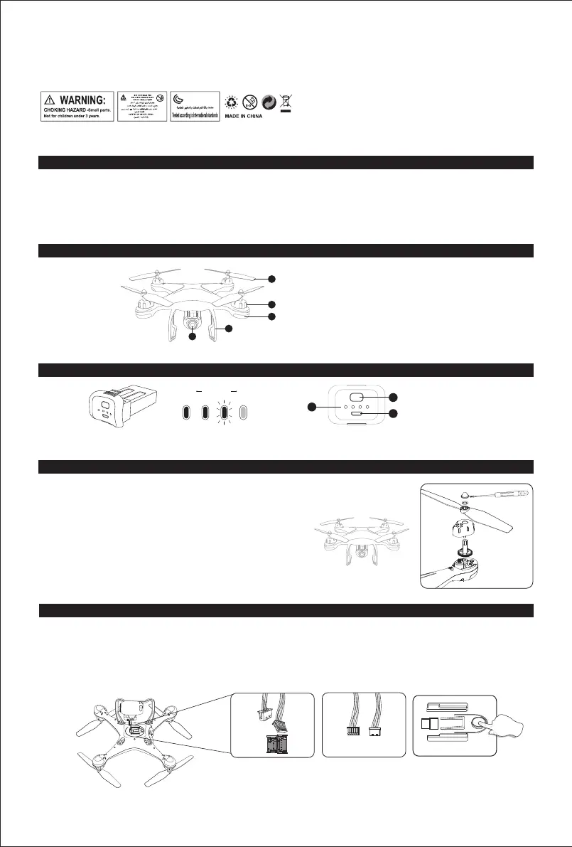
WARNING: CHARGING OF THE DRONE BATTERY MUST BE SUPERVISED AT ALL TIMES BY AN ADULT. UNPLUG THE BATTERY WHEN FULLY
CHARGED. DO NOT OVER-CHARGE THE BATTERY.
Low Electricity High
WARNING: Product should only be used by adults and children 14 years
and older. Adult supervision required for children under 14 years of age.
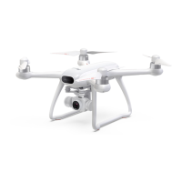
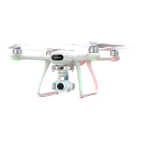
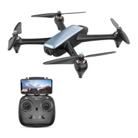
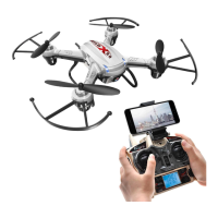
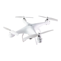
1. HD Camera
2. Landing Gear
3. Propeller
4. Motor
5. LED Indicator
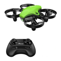
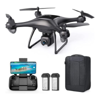
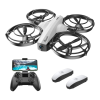
1. Battery Power Indicator
2. USB Charging Port
3. Battery Switch
MAINTENANCE
1. Use a clean soft cloth to clean this product frequently.
2. Avoid heating or prolonged exposure to the sun.
3. Don’t put the product in water. It will damage electronic parts.
4. Please check the plug and other accessories atregular intervals. If there is any damage, please stop using it immediately until it is
repaired completely.
QUADROTOR LI-POLYMER
DRONE PARTS
Press the battery shortly to switch on, hold for 2 seconds to switch it off.
Gear
Cap
Spacer Ring
Propeller
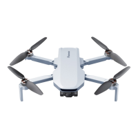
ASSEMBLE THE PROPELLER
Please note that the letter “A” or “B” is printed on each propeller, and make sure all the propellers are
attached in the correct motor position.
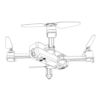
1. Plug the camera wires accordingly into the connection ports on the bottom of the drone. (Smaller wire connects to small port while the
Bigger wire connects to big port Pic. 1. Wire connector has two sides A/B Pic. 2, A side of the small interface faces drone’s Head and A side
of Bigger interface faces drone’s Tail direction).
2. Push the camera into the camera installation track on the bottom of the drone.
3. Remove camera by pressing the camera lock Pic. 3.on the bottom of the drone, and push the camera out to disconnect the camera wire
from the port.
Pic.1 Pic.2
ASSEMBLE THE CAMERA
A
B
B
A
1. Unscrew the Propeller Cap
2. Remove the Propeller Cap
3. Remove the pad and the blade
1
2
3
1
2
5
3
4
4. Attach the correct propeller and the pad
5. Attach the Propeller Cap
6. Tighten the screws
02
25. To comply with the command of the magnetic environment requirement formulated by the Aviation Radio Bureau and the related authority, during the
regulated period in certain areas, please stop using the transmitter of this model when such regulation command is issued.
26. Keep your UAS within sight.
27. Never fly over groups of people.
28. Never fly over stadiums or sports events.
29. Understand airspace restrictions and requirements.
 Loading...