Installation Manual: PAD200-DUCT Analog Addressable Duct Detector
NOTICE TO THE INSTALLER
This manual provides an overview and the installation instructions for the PAD200-DUCT module. This module is only compatible
with addressable re systems that utilize the PAD Addressable Protocol.
All terminals are power limited and should be wired in accordance with the requirements of NFPA 70 (NEC) and NFPA 72 (National
Fire Alarm Code). Failure to follow the wiring diagrams in the following pages will cause the system to not operate as intended. For
further information, refer to the control panel installation instructions.
The module shall only be installed with listed control panels. Refer to the control panel installation manual for proper system
operation.
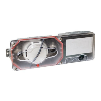
1. Description
The PAD200-DUCT duct smoke detector provides early detection of smoke and products of combustion present in the air moving
through HVAC ducts in commercial, industrial and residential applications. The PAD200-DUCT is designed and built to meet all
local requirements, as well as the NFPA regulations regarding duct smoke detectors.
Air sampling is accomplished by two tubes which protrude into the duct. An exhaust tube of one standard length (7") is supplied
in the installation kit with the smoke duct unit. Once the duct width has been determined, the air intake sampling tubes must be
ordered. Sampling tubes are supplied in three standard lengths: 2.5 ft., 5 ft., and 10 ft. and cut to size to t the duct. Mounting
the duct smoke unit is accomplished by the use of a template and 2 sheet metal screws, which are provided. Mounting can be
achieved without the removal of the clear cover which is secured by 4 capture screws.
2. Setting the Address
All PAD protocol detectors and modules require an address prior to connection to the panel's SLC loop. Each PAD device's
address (i.e., detector and/or module) is set by changing the dip switches located on the device. PAD device addresses are
comprised of a seven (7) position dip switch used to program each device with an address ranging from 1–127.
Figure 1. PAD Device Dip Switch Addresses Table (Addresses 1–127)
Note: Each "gray" box indicates that the dip switch is "On," and each "white" box indicates "O."
Document 5406428-A 02/21
Potter Electric Signal Company, LLC • St. Louis, MO • Phone: (800) 325-3936 • www.pottersignal.com
PAGE 1 OF 4
124816 32 64 124816 32 64 124816 32 64 124816 32 64 1248163264
1275378103
2285479104
3295580105
4305681106
5315782107
6325883108
7335984109
8346085110
9356186111
10 36 62 87 112
11 37 63 88 113
12 38 64 89 114
13 39 65 90 115
14 40 66 91 116
15 41 67 92 117
16 42 68 93 118
17 43 69 94 119
18 44 70 95 120
19 45 71 96 121
20 46 72 97 122
21 47 73 98 123
22 48 74 99 124
23 49 75 100125
24 50 76 101126
25 51 77 102127
26 52 124816 32 64 124816 32 64 1248163264
124816 32 64 124816 32 64