INSTALLATION MANUAL: PAD200-DUCT ANALOG ADDRESSABLE DUCT DETECTOR
Document 5406428-A 02/21
Potter Electric Signal Company, LLC • St. Louis, MO • Phone: (800) 325-3936 • www.pottersignal.com
PAGE 2 OF 4
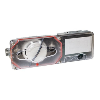
The examples shown below illustrate a PAD device's dip switch settings: the 1st example shows a device not addressed where all
dip switch settings are in the default "O" position, the 2nd illustrates an addressed PAD device via the dip switch settings.
Figure 2. Examples of PAD Device Showing Default Dip Switch Setting (Unaddressed) & Addressed PAD Device
Before connecting a device to the SLC loop, take the following precautions to prevent potential damage to the SLC or device.
• Power to the SLC is removed.
• Field wiring on module is correctly installed.
• Field wiring has no open or short circuits.
3. Technical Specications
Duct Detector Model # PAD200-DUCT
Operating Voltage 24.0V
Current Draw 300μA
Detector Head Model PAD200-DD
Detector Head Type Photoelectric
Sensitivity Test Method Self diagnostic test
Air Velocity 100 to 4000 ft./min.
Ambient Temperature
32 to 120 F (0 to 49 C)
Humidity 10% to 85% Relative humidity (non-condensing)
Housing Material Plastic backbox, clear plastic cover
Finish Gray backbox with clear cover
Dimensions 13 1/2" L x 4 1/2" W x 2 1/4" D
Maximum Net Weight 2 lbs.
Sampling Tubes 2.5 ft., 5 ft., or 10 ft.
Sampling Tube Part Numbers 2.5' = 1000274, 5' = 1000275, 10' = 1000276
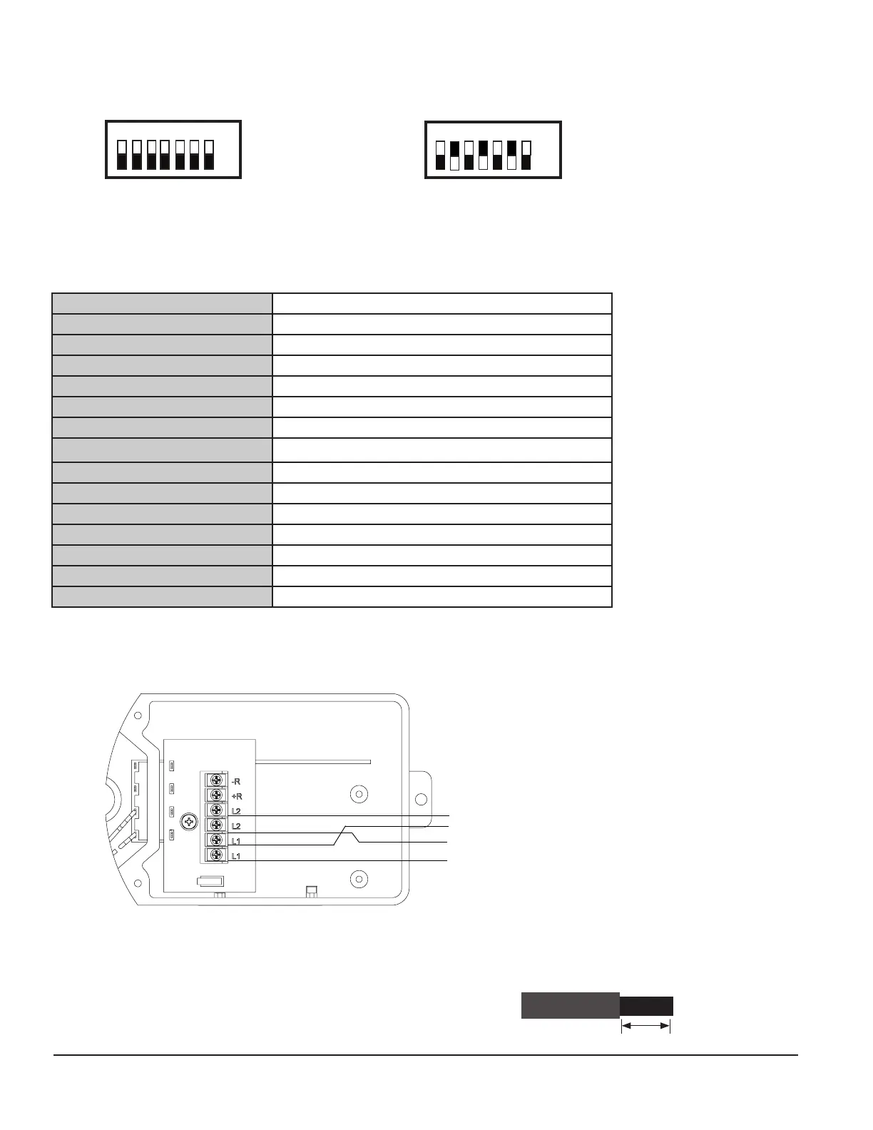
4. Wiring Diagram
The wiring diagram shown below illustrates how to wire a PAD200-DUCT duct detector.
Figure 3. Example of Wiring a PAD200-DUCT Duct Detector
Notes:
• SLC wiring style supports the Class A, Class X and Class B.
• SLC loop wiring is power limited.
• SLC loop wiring is supervised.
• Wiring for terminals are supervised.
• All wiring is between #12 (max.) and #22 (min.).
• Wire Preparation – Strip all wires 1/4 inch from their edges as shown here:
– Stripping too much insulation may cause a ground fault.
– Stripping too little may cause a poor connection and subsequently an open circuit.
1/4 inch
+SLC
-SLC
-SLC
FROM FACP or
PREVIOUS MODULE
TO NEXT MODULE
+SLC
Off
On
1 2 4 16
8 32 64
All dip switches are
shown in the "O"
position.
Off
On
1 2 4 16
8
32 64
Example shows this PAD device's
address = 42. Dip switches #2, 8 &
32 are in the "On" position.
 Loading...