MFG. #5400928 - REV D
1/08
PRINTED IN USA PAGE 3 OF 3
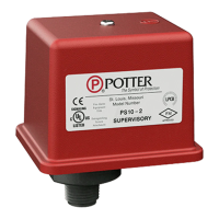
MODEL PS10
PRESSURE SWITCH
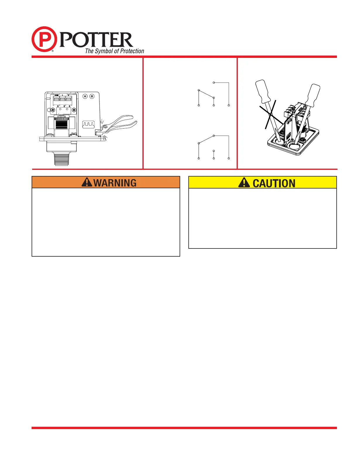
Break out thin section of divider to provide path for wires
when wiring both switches from one conduit entrance.
One Conduit Wiring
Fig. 7
Fig. 9
Removing Knockouts
W/ PRESSURE APPLIED
W/O PRESSURE APPLIED
NC
NO
C
C 1 2
NC
NO
C
C 1 2
Changing Pressure
Fig. 8
•Installation must be performed by qualifi ed personnel and in
accordance with all national and local codes and ordinances.
•Shock hazard. Disconnect power source before servicing.
Serious injury or death could result.
•Read all instructions carefully and understand them before
starting installation. Save instructions for future use. Failure to
read and understand instructions could result in improper
operation of device resulting in serious injury or death.
•Risk of explosion. Not for use is hazardous locations. Serious
injury or death could result.
•Do not tighten by grasping the switch enclosure. Use wrenching
fl ats on the bushing only. Failure to install properly could damage
the switch and cause improper operation resulting in damage to
equipment and property.
•To seal threads, apply Tefl on tape to male threads only. Using
joint compounds or cement can obstruct the pressure port inlet
and result in improper device operation and damage to equipment.
•Do not over tighten the device, standard piping practices apply.
Engineer/Architect Specifi cations Pressure Type
Waterfl ow Switch
Pressure type waterfl ow switches; shall be a Model PS10 as
manufactured by Potter Electric Signal Company, St Louis MO.,
and shall be installed on the fi re sprinkler system as shown and or
specifi ed herein.
Switches shall be provided with a ½” NPT male pressure connection
and shall be connected to the alarm port outlet of; Wet Pipe Alarm
Valves, Dry Pipe Valves, Pre-Action Valves, or Deluge Valves. The
pressure switch shall be actuated when the alarm line pressure reaches
4 - 8 PSI (0,27 - 0,55 BAR).
Pressure type waterfl ow switches shall have a maximum service
pressure rating of 300 PSI (20,68 BAR) and shall be factory adjusted
to operate on a pressure increase of 4 - 8 PSI (0,27 - 0,55 BAR)
Pressure switch shall have one or two form C contacts, switch contact
rating 10.1 Amps at 125/250 VAC, 2.0 Amps at 30 VDC.
Pressure type waterfl ow switches shall have two conduit entrances
one for each individual switch compartment to facilitate the use of
dissimilar voltages for each individual switch.
The cover of the pressure type waterfl ow switch shall be Zinc die-cast
with rain lip and shall attach with one tamper resistant screw. The
Pressure type waterfl ow switch shall be suitable for indoor or outdoor
service with a NEMA 4/IP55 rating.
The pressure type waterfl ow switch shall be UL Ulc and CSFM listed,
FM and LPC approved and NYMEA accepted.
For low pressure use:
Com and Terminal 1
For waterfl ow use:
Com and Terminal 2
 Loading...