PAGE 1 OF 2PRINTED IN USA MKT. #8800001 - REV W
MFG. #5400761 - 7/02
VSR-F
VANE TYPE WATERFLOW
ALARM SWITCH WITH RETARD
UL, ULC and CSFM Listed, FM and LPCB Approved, NYMEA
Accepted, CE Marked
Service Pressure: Up to 450 PSI (31 BAR)
Minimum Flow Rate for Alarm: 10 GPM (38 LPM)
Maximum Surge: 18 FPS (5,5 m/s)
Contact Ratings: Two sets of SPDT (Form C)
15.0 Amps at 125/250VAC
2.0 Amps at 30VDC Resistive
Conduit Entrances: Two knockouts provided for 1/2" conduit
Environmental Specifi cations:
• Suitable for indoor or outdoor use with factory installed gasket and
die-cast housing.
• NEMA 4/IP54 Rated Enclosure - use with appropriate conduit
fi tting.
• Temperature Range: 40°F/120°F, 4,5°C/49°C
• Non-corrosive sleeve factory installed in saddle.
Caution: This device is not intended for applications in explosive
environments.
Sizes Available: Steel Pipe schedules 10 thru 40, sizes 2" thru 8"
BS 1387 pipe 50mm thru 200mm
Note: For copper or plastic pipe use Model VSR-CF.
Service Use:
Automatic Sprinkler NFPA-13
One or two family dwelling NFPA-13D
Residential occupancy up to four stories NFPA-13R
National Fire Alarm Code NFPA-72
Optional: Cover Tamper Switch Kit, Stock No. 0090018
U.S. Pat. No. 3921989
Canadian Pat. No. 1009680
Other Patents Pending
Potter Electric, Rd., 1990
GENERAL INFORMATION
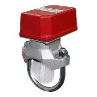
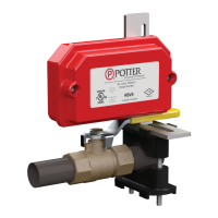
The Model VSR-F is a vane type waterfl ow switch for use on wet
sprinkler systems. It is UL Listed and FM Approved for use on steel
pipe; schedules 10 through 40, sizes 2" thru 8" (50mm thru 200mm).
LPC approved sizes are 2" thru 8" (50mm thru 200mm).
The unit may also be used as a sectional waterfl ow detector on large
systems.
The unit contains two single pole, double throw, snap action switches
and an adjustable, instantly recycling pneumatic retard. The switches
are actuated when a fl ow of 10 gallons per minute (38 LPM) or more
occurs downstream of the device. The fl ow condition must exist for a
period of time necessary to overcome the selected retard period.
ENCLOSURE: The unit is enclosed in a general purpose, die-cast
housing. The cover is held in place with two tamper resistant screws
which require a special key for removal. A fi eld installable cover
tamper switch is available as an option which may be used to indicate
unauthorized removal of the cover. See bulletin no. 5400775 for
installation instructions of this switch.
INSTALLATION: See Fig.2
These devices may be mounted on horizontal or vertical pipe. On
horizontal pipe they should be installed on the top side of the pipe
where they will be accessible. The units should not be installed within
6" (15cm) of a fi tting which changes the direction of the waterfl ow or
within 24" (60 cm) of a valve or drain.
Drain the system and drill a hole in the pipe using a circular saw in a
slow speed drill. The 2" (50mm) and 2 1/2" (65mm) devices require a
hole with a diameter of 1 1/4" + 1/8" - 1/16" (33mm ±2mm). All other
sizes require a hole with a diameter of 2" ±1/8" (50mm ±2mm).
Clean the inside pipe of all growth or other material for a distance equal
to the pipe diameter on either side of the hole.
Roll the vane so that it may be inserted into the hole; do not bend or
crease it. Insert the vane so that the arrow on the saddle points in the
direction of the waterfl ow. Install the saddle strap and tighten nuts
alternately to an eventual 50 ft-lbs. (68 n-m) of torque (see Fig. 2). The
vane must not rub the inside of the pipe or bind in any way.
Specifi cations subject to change without notice.
Potter Electric Signal Company • 2081 Craig Road, St. Louis, MO, 63146-4161 • Phone: 800-325-3936/Canada 888-882-1833
• www.pottersignal.com