PAGE 2 OF 2PRINTED IN USA MKT. #8800001 - REV W
MFG. #5400761 - 7/02
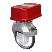
VSR-F
VANE TYPE WATERFLOW
ALARM SWITCH WITH RETARD
NOTES:
1. The Model VSR-F has two
switches, one can be used
to operate a central station,
proprietary or remote signaling
unit, while the other contact is
used to operate a local audible or
visual annunciator.
2. A condition of LPC Approval of
this product is that the electrical
entry must be sealed to exclude
moisture.
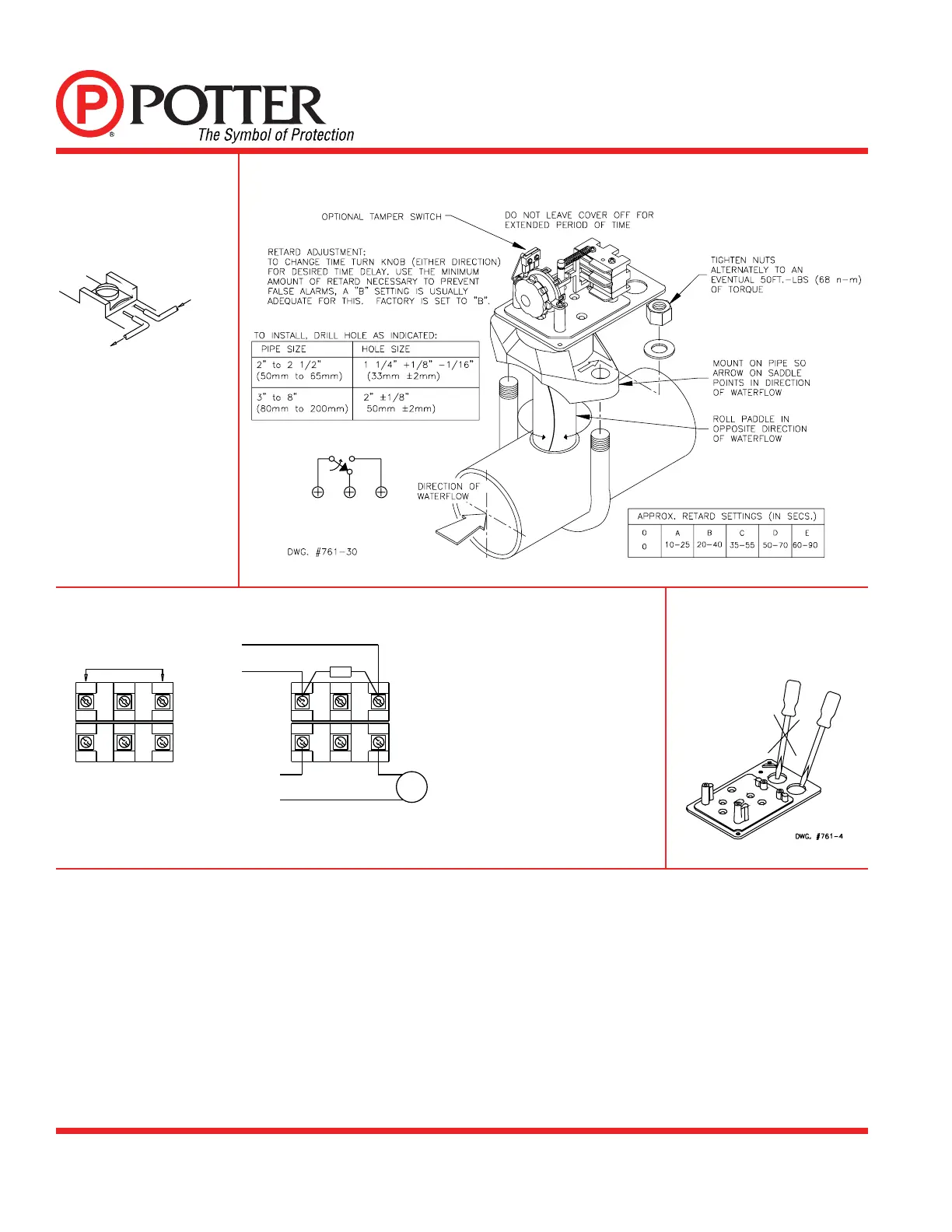
3. For supervised circuits see
“Switch Terminal Connections”
drawing and caution note
(Fig. 1).
SWITCH TERMINAL
CONNECTIONS
CLAMPING PLATE
TERMINAL
CAUTION:
An uninsulated section of a
single conductor should not
be looped around the terminal
and serve as two separate
connections. The wire must
be severed, thereby providing
supervision of the connection
in the event that the wire
becomes dislodged from under
the terminal.
TESTING
The frequency of inspection and testing for the model VSR-F and its associated protective monitoring system should be in accordance with
applicable NFPA Codes and Standards and/or the authority having jurisdiction (manufacturer recommends quarterly or more frequently).
If provided, the inspector’s test valve, that is usually located at the end of the most remote branch line, should always be used for test purposes.
If there are no provisions for testing the operation of the fl ow detection device on the system, application of the VSR-F is not recommended or
advisable.
A minimum fl ow of 10 gpm (38 Lpm) is required to activate this device.
IMPORTANT NOTICE: Please advise the person responsible for testing of the fi re protection system that this system must be tested in
accordance with the testing instructions.
FIG. 1 FIG. 2
FIG. 3 TYPICAL ELECTRICAL CONNECTIONS
OUTGOING
INCOMI
DWG# 923-3
FIG. 4
To remove knockouts: Place
screwdriver at edge of knockouts,
not in the center.
APPLICATION WARNING!
Due to the possibility of unintended discharges caused by pressure surges, trapped air, or short retard times, waterfl ow switches that are
monitoring wet pipe sprinkler systems should not be used as the sole initiating device to discharge AFFF, deluge, or chemical suppression
systems.
2 SETS OF NORMALLY
OPEN CONTACTS
CLOSE ON ALARM
THE N.C. AND N.O. MARKINGS ON
THE SWITCH ARE FOR AN ALARM
CONDITION.
THE CONTACTS ARE REVERSED
WHEN THE DEVICE IS IN THE
NORMAL CONDITION.
WATERFLOW ZONE
ON FIRE PANEL
EOLR FROM
FIRE PANEL
POSITIVE DC
OR HOT AC
NEGATIVE DC OR
NEUTRAL AC
DWG# 761-2
BELL
COM
NO NC
COM
NO NC
COM
NO NC
COM
NO NC
EOLR
DWG# 8810018-2
C
(WHT)
N.O.
(RED)
N.C.
(BLK)
Cover Tamper
(with cover in place)

 Loading...