PRINTED IN USA PAGE 1 OF 4
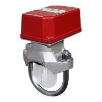
VSR
VANE TYPE WATERFLOW
ALARM SWITCH WITH RETARD
MFG. #5401146 - REV M
11/15
UL, CUL and CSFM Listed, FM Approved, LPCB Approved, For
CE Marked (EN12259-5) / VdS Approved model use VSR-EU
Service Pressure: 450 PSI (31 BAR) - UL
Flow Sensitivity Range for Signal:
4-10 GPM (15-38 LPM) - UL
Maximum Surge: 18 FPS (5.5 m/s)
Contact Ratings: Two sets of SPDT (Form C)
10.0 Amps at 125/250VAC
2.0 Amps at 30VDC Resistive
10 mAmps min. at 24VDC
Conduit Entrances: Two knockouts provided for 1/2" conduit.
Individual switch compartments suitable
for dissimilar voltages.
Environmental Specications:
• NEMA4/IP54RatedEnclosuresuitableforindooror
outdoor use with factory installed gasket and die-cast housing
whenusedwithappropriateconduittting.
• TemperatureRange:40°F-120°F,(4.5°C-49°C)-UL
• Non-corrosivesleevefactoryinstalledinsaddle.
Service Use:
AutomaticSprinkler NFPA-13
Oneortwofamilydwelling NFPA-13D
Residentialoccupancyuptofourstories NFPA-13R
NationalFireAlarmCode NFPA-72
• Installationmustbeperformedbyqualiedpersonnelandin
accordance with all national and local codes and ordinances.
•Shockhazard.Disconnectpowersourcebeforeservicing.Serious
injury or death could result.
•Riskofexplosion.Notforuseinhazardouslocations.Serious
injury or death could result.
Ordering Information
NominalPipeSize Model PartNumber
2" DN50 VSR-2 1144402
2 1/2" DN65 VSR-2 1/2 1144425
3" DN80 VSR-3 1144403
3 1/2" - VSR-3 1/2 1144435
4" DN100 VSR-4 1144404
5" - VSR-5 1144405
6" DN150 VSR-6 1144406
8" DN200 VSR-8 1144408
Specicationssubjecttochangewithoutnotice.
Optional:CoverTamperSwitchKit,stockno.0090148
Replaceable Components:Retard/SwitchAssembly,stockno.1029030
Waterowswitchesthataremonitoringwetpipesprinklersystemsshall
notbeusedasthesoleinitiatingdevicetodischargeAFFF,deluge,
orchemicalsuppressionsystems.Waterowswitchesusedforthis
application may result in unintended discharges caused by surges,
trappedair,orshortretardtimes.
Potter Electric Signal Company, LLC• St. Louis, MO • Phone: 866-956-1211/Canada 888-882-1833
• www.pottersignal.com
General Information
TheModelVSRisavanetypewaterowswitchforuseonwetsprinkler
systems.ItisULListedforuseonasteelpipe;schedules5through40,
sizes2"-6"andisULListedandFMApprovedforuseonsteelpipe;
schedules10through40,sizes2"thru8"(50mmthru200mm).LPC
approvedsizes are 2" thru 8" (50 mm thru 200 mm). See Ordering
Information chart.
TheVSRmayalsobeusedasasectionalwaterowdetectoronlarge
systems.TheVSRcontainstwosinglepole,doublethrow,snapaction
switchesandanadjustable,instantlyrecyclingpneumaticretard.The
switchesareactuatedwhenaowof10GPM(38LPM)ormoreoccurs
downstreamofthedevice.Theowconditionmustexistforaperiod
of time necessary to overcome the selected retard period.
Enclosure
TheVSRswitchesandretarddeviceareenclosedinageneralpurpose,
die-cast housing. The cover is held in place with two tamper resistant
screws which require a special key for removal. A eldinstallable
cover tamper switch is available as an option which may be used
to indicate unauthorized removal of the cover. See bulletin number
5401103 for installation instructions of this switch.
Important: This document contains important information on the installation and operation of theVSR waterow switches. Please read all
instructionscarefullybeforebeginninginstallation.AcopyofthisdocumentisrequiredbyNFPA72tobemaintainedonsite.