PRINTED IN USA MFG. #5401146 - REV M
11/15
PAGE 2 OF 4
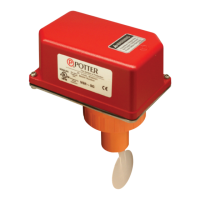
VSR
VANE TYPE WATERFLOW
ALARM SWITCH WITH RETARD
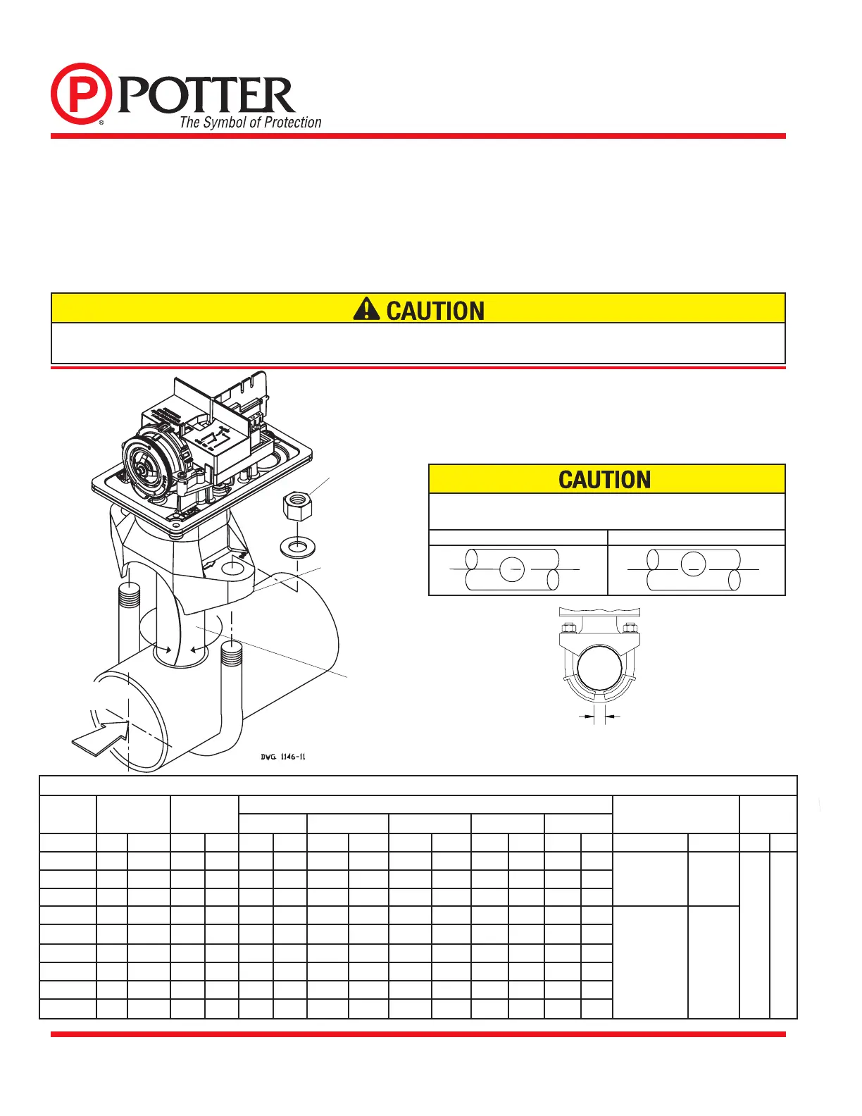
Installation (see Fig. 1)
Thesedevicesmaybemountedonhorizontalorverticalpipe.Onhorizontalpipetheyshallbeinstalledonthetopsideofthepipewherethey
willbeaccessible.Thedeviceshouldnotbeinstalledwithin6"(15cm)ofattingwhichchangesthedirectionofthewateroworwithin24"
(60cm)ofavalveordrain.
NOTE:Donotleavecoveroffforanextendedperiodoftime.
Drain the system and drill a hole in the pipe using a hole saw in a slow speed drill (see Fig. 1). Clean the inside pipe of all growth or other
material for a distance equal to the pipe diameter on either side of the hole. Roll the vane so that it may be inserted into the hole; do not bend
orcreaseit.Insertthevanesothatthearrowonthesaddlepointsinthedirectionofthewaterow.Takecarenottodamagethenon-corrosive
bushinginthesaddle.Thebushingshouldtinsidetheholeinthepipe.Installthesaddlestrapandtightennutsalternatelytorequiredtorque
(see the chart in Fig. 1). The vane must not rub the inside of the pipe or bind in any way.
ADAPTER
USE (2) 5180162 ADAPTERS AS SHOWN ABOVE
DN50 ONLY
ADAPTER
50mm
20mm ±2mm MAX.
DWG# 1146-1F
Fig. 1
NOTE:ForcopperorplasticpipeuseModelVSR-CF.
Retard Adjustment
The delay can be adjusted by rotating the retard adjustment knob from
0tothemaxsetting(60-90seconds).Thetimedelayshouldbesetat
the minimum required to prevent false alarms
(Flowing water activates
device in one direction only.)
DO NOT LEAVE COVER OFF FOR
AN EXTENDED PERIOD OF TIME
TIGHTENNUTS
ALTERNATELY
MOUNTONPIPESO
ARROWONSADDLE
POINTSINDIRECTION
OF WATERFLOW
ROLLPADDLEIN
OPPOSITEDIRECTION
OF WATERFLOW
DIRECTIONOF
WATERFLOW
Hole must be drilled perpendicular to the pipe and vertically centered.
RefertotheCompatiblePipe/InstallationRequirementschartforsize.
Correct
Incorrect
Compatible Pipe/ Installation Requirements
Model NominalPipe
Size
NominalPipe
O.D.
Pipe Wall Thickness HoleSize U-BoltNuts
Torque
Lightwall
Schedule 10 (UL) Schedule 40 (UL) BS-1387(LPC) DN(VDS)
inch mm inch mm inch mm inch mm inch mm inch mm inch mm inch mm ft-lb n-m
VSR-2 2 DN50 2.375
60.3
.065 1.651 0.109 2.77 0.154 3.91 0.142 3.6 0.091 2.3
1.25 + .125/-
.062
33.0 ± 2.0
20 27
VSR-2 1/2 2.5 - 2.875 73.0 .084 2.134 0.120 3.05 0.203 5.16 - - - -
VSR-2 1/2 - DN65 3.000 76.1 - - - - - - 0.142 3.6 0.102 2.6
VSR-3 3 DN80 3.500 88.9 .083 2.108 0.120 3.05 0.216 5.49 0.157 4.0 0.114 2.9
2.00 ± .125 50.8 ± 2.0
VSR-3 1/2 3.5 - 4.000 101.6 - - 0.120 3.05 0.226 5.74 - - - -
VSR-4 4 DN100 4.500 114.3 .084 2.134 0.120 3.05 0.237 6.02 0.177 4.5 0.126 3.2
VSR-5 5 - 5.563 141.3 - - 0.134 3.40 0.258 6.55 - - - -
VSR-6 6 DN150 6.625 168.3 .115 2.921 0.134 3.40 0.280 7.11 0.197 5.0 0.157 4.0
VSR-8 8 DN200 8.625 219.1 - - 0.148 3.76 0.322 8.18 0.248 6.3 0.177 4.5
Do not trim the paddle. Failure to follow these instructions may prevent the device from operating and will void the warranty. Do not obstruct or otherwise prevent
thetripstemoftheowswitchfrommovingwhenwaterowsasthiscoulddamagetheowswitchandpreventanalarm.Ifanalarmisnotdesired,aqualied
technician should disable the alarm system.
 Loading...