PRINTED IN USA PAGE 3 OF 4
VSR
VANE TYPE WATERFLOW
ALARM SWITCH WITH RETARD
MFG. #5401146 - REV M
11/15
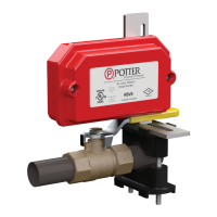
Toremoveknockouts:Placescrewdriverat
insideedgeofknockouts,notinthecenter.
Fig. 2
Do not drill into the base as this creates
metal shavings which can create
electricalhazardsanddamagethe
device. Drilling voids the warranty.
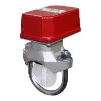
Fig. 4 Switch Terminal Connections Clamping
Plate Terminal
Fig. 3
Break out thin section of cover when
wiring both switches from one conduit
entrance.
Testing
The frequency of inspection and testing for the Model VSR and its associated protective monitoring system shall be in accordance with applicable
NFPACodesandStandardsand/ortheauthorityhavingjurisdiction(manufacturerrecommendsquarterlyormorefrequently).
Ifprovided,theinspector’stestvalveshallalwaysbeusedfortestpurposes.Iftherearenoprovisionsfortestingtheoperationoftheowdetection
deviceonthesystem,applicationoftheVSRisnotrecommendedoradvisable.
Aminimumowof10GPM(38LPM)isrequiredtoactivatethisdevice.
Advise the person responsible for testing of the fire protection system that this system must be tested in accordance
with the testing instructions.
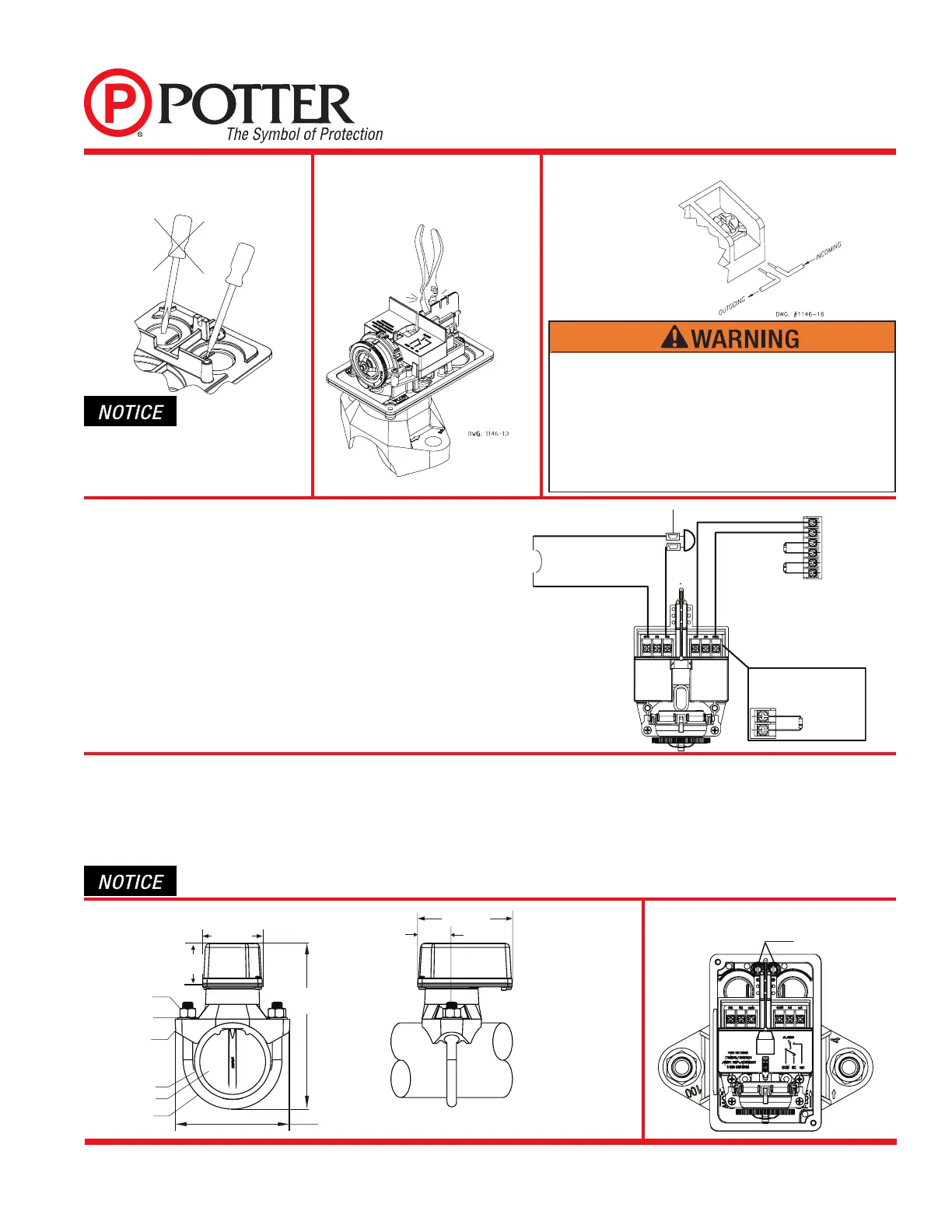
Fig. 6 Mounting Dimensions
DWG. 1146-14
3.50 in
(89.0mm)
2.34 in
(59.4mm)
PIPE DIA.
+ 5.25 in
(+ 133.4 mm)
5.56in
(141.2 mm)
2.00 in
(50.8 mm)
U-BOLTNUT
U-BOLT WASHER
PIPE SADDLE
PIPE
PLASTIC PADDLE
U-BOLT
NOMINALPIPEDIA.+1.75in(+44.5MM)FORDN50–DN652–2.5in
NOMINALPIPEDIA.+2.125in(+54.0MM)FORDN80–DN2003–8in
GREENGROUND
SCREWS
Fig. 7
An uninsulated section of a single conductor should not be looped
around the terminal and serve as two separate connections. The
wiremustbesevered,therebyprovidingsupervisionofthe
connection in the event that the wire become dislodged from under
the terminal. Failure to sever the wire may render the device
inoperable risking severe property damage and loss of life.
Donotstripwirebeyond3/8"oflengthorexposeanuninsulated
conductor beyond the edge of the terminal block. When using
strandedwire,captureallstrandsundertheclampingplate.
Notes:
1. TheModelVSRhastwoswitches,onecanbeusedtooperateacentral
station,proprietaryorremotesignalingunit,whiletheothercontact
is used to operate a local audible or visual annunciator.
2. Forsupervisedcircuits,see“SwitchTerminalConnections”
drawing and warning note (Fig. 4).
Fig. 5 Typical Electrical Connections
LOAD TO BELL
NEUTRAL FROM BELL
EOL (End Of Line Resistor)
BELL
NEUTRAL FROM
BREAKER
BREAKER
LINE FROM BREAKER
NOTE:
When connecting to a UL Listed
control panel, use the panel’s
resistor value for circuit supervision.
 Loading...