PRINTED IN USA MFG. #5401146 - REV M
11/15
PAGE 4 OF 4
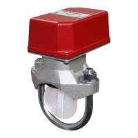
VSR
VANE TYPE WATERFLOW
ALARM SWITCH WITH RETARD
Removal of Waterow Switch
• Topreventaccidentalwaterdamage,allcontrolvalvesshouldbeshuttightandthesystemcompletelydrainedbeforewaterowdetectorsare
removed or replaced.
•Turnoffelectricalpowertothedetector,thendisconnectwiring.
•LoosennutsandremoveU-bolts.
•Gentlyliftthesaddlefarenoughtogetyourngersunderit.Withyourngers,rollthevanesoitwilltthroughtheholewhilecontinuing
toliftthewaterowdetectorsaddle.
•Liftdetectorclearofpipe.
Fig. 8
Retard/Switch Assembly Replacement (See Fig. 8)
TheRetard/SwitchAssemblyiseld-replaceablewithoutdrainingthesystemorremovingthewaterowswitchfromthe
pipe
1. Makesuretherealarmzoneorcircuitconnectedtothewaterowswitchisbypassedorotherwisetakenoutofservice.
2. Disconnect the power source for local bell (if applicable).
3. Identifyandremoveallwiresfromthewaterowswitch.
4. Remove the (2) mounting screws holding retard/switch assembly to the base. Do not remove the (2) retard housing screws.
5. Remove the retard assembly by lifting it straight up over the tripstem.
6. Installthenewretardassembly.Makesurethelocatingpinsontheretard/switchassemblytintothelocatingpinbossesonthebase.
7. Re-install the (2) original mounting screws.
8. Reconnectallwires.Performaowtestandplacethesystembackinservice.
Maintenance
Inspectdetectors monthly. If leaksare found,replace the detector. TheVSRwaterow switchshould provide yearsof trouble-freeservice.
Theretardandswitchassemblyareeasilyeldreplaceable.Intheunlikelyeventthateithercomponentdoesnotperformproperly,pleaseorder
replacementretardswitchassemblystock#1029030(seeFig.8).Thereisnomaintenancerequired,onlyperiodictestingandinspection.
DWG# 1146-10
BREAKOUTTHINSECTIONOFCOVER
WHEN WIRING BOTH SWITCHES
FROMONECONDUITENTRANCE.
DO NOT REMOVE
(2)RETARDHOUSING
SCREWS
REMOVE(2)ORIGINALMOUNTING
SCREWSHOLDINGRETARD/SWITCH
ASSEMBLYTOBASE
RETARD/SWITCHASSEMBLY
(2)ORIGINALMOUNTING
SCREWS
(2)LOCATINGPINS
(2)LOCATINGPIN
BOSSESINBASE
BASE