PRINTED IN USA PAGE 1 OF 4MFG. #5401205 - REV H
01/12
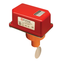
VSR-SG
VANE TYPE WATERFLOW
ALARM SWITCH WITH RETARD
AND GLUE-IN UNION
FOR CPVC PIPE
Do not over-tighten the union nut, hand tighten only. Use of a wrench
may damage the union nut.
Do not trim the paddle. Failure to follow these instructions may prevent the
switch from operating and will void the warranty.
General Information
period of time necessary to overcome the selected retard period.
UL, CUL and CSFM Listed, CE Marked
Service Pressure:
Flow Sensitivity Range for Signal:
Maximum Surge:
Contact Ratings:
10.0 Amps at 125/250VAC
10 mAmps min. at 24VDC
Conduit Entrances: Two openings provided for 1/2" conduit.
for dissimilar voltages.
Environmental Specications:
outdoor use with factory installed gasket and die-cast housing
Service Use:
National Fire Alarm Code NFPA-72
accordance with all national and local codes and ordinances.
injury or death could result.
injury or death could result.
Stock Number: 1144460
Optional
Replaceable Components:
Enclosure
The VSR-SG switches and retard switch are enclosed in a general
purpose, die-cast housing. The cover is held in place with two tamper
trapped air, or short retard times.
www.pottersignal.com
Installation (
for gluing into a CPVC plastic tee.
NOTE:
TEE
for instructions on how to change paddle. Verify that the o-ring is
properly positioned in its groove. Hand tighten the nut on the union
as shown in Fig. 5 & Fig. 7.