Do you have a question about the Potterton 24 Eco HE and is the answer not in the manual?
Details relevant British Standards and Irish Codes of Practice for gas installation.
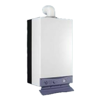
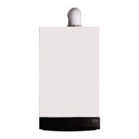
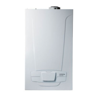
Provides a description of the Potterton Performa 24 Eco HE boiler and its features.
Lists available optional accessories for the boiler, detailed separately.
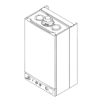
Identifies and lists the components of the boiler with corresponding numbers in diagrams.
Explains how the boiler operates in central heating mode, including burner ignition and temperature control.
Details the boiler's operation for domestic hot water, highlighting priority and temperature control.
Details appliance type, category, gas supply, burner, and inlet pressures for Natural Gas and LPG.
Specifies heat input and output for Central Heating (condensing/non-condensing) and Domestic Hot Water.
Covers electrical supply, power consumption, fuse ratings, and system pressures.
Includes flue terminal dimensions and pump performance curves.
Details operating temperatures and the SEDBUK efficiency rating.
Provides overall dimensions (A, B, C) of the boiler and flue diameter (D).
Details pipe connections, clearances, and fixing points for installation.
Covers water byelaws compliance and general system information.
Details requirements for sealed central heating systems, including flushing and inhibitor use.
Mentions the presence of an automatic integral bypass.
Discusses external controls, timers, and thermostat recommendations for system control.
Explains the process for filling and pressurising the central heating system.
Details the pre-charge pressure and capacity of the expansion vessel.
Describes the set pressure and discharge pipe requirements for the pressure relief valve.
Outlines requirements for DHW circuits, including check valves and expansion vessels.
Provides recommendations for shower controls and their compatibility.
Advises on treatment devices for installations in hard water areas.
Specifies suitable locations for boiler installation, considering ventilation and regulations.
Details necessary clearances around the boiler for access, servicing, and air movement.
Addresses ventilation needs when the boiler is installed in a cupboard or compartment.
Specifies gas installation standards and connection details.
Covers wiring regulations, mains supply, and isolation requirements.
Details requirements for condensate discharge pipework, including fall, material, and termination.
Provides general guidelines for siting balanced flue terminals, referencing standards.
Lists minimum distances for flue terminals from openings and boundaries.
Specifies the allowable lengths for standard horizontal flue kits.
Describes the fitting of the rubber flue trim.
Explains the purpose, sourcing, and fitting of flue terminal guards.
Illustrates different flue configurations and their maximum permissible equivalent lengths.
Covers checking gas supply, positioning the fixing template, and preparing the wall.
Details the process of flushing the central heating system before boiler installation.
Instructs on removing packaging and positioning the boiler for fitting.
Explains how to mount the boiler onto the wall plate and connect water/gas supplies.
Guides on routing and connecting the pressure relief discharge pipework.
Details connecting the condensate drain pipe, referencing previous section.
Explains the process of fitting the horizontal flue elbow and measuring wall thickness.
Continues flue fitting instructions, including cutting, centralizing, and making good.
Mentions suitability of approved vertical flues and refers to a separate brochure.
Details how to make mains and external control electrical connections to the boiler.
Outlines essential electrical system checks before commissioning the boiler.
Guides through initial boiler commissioning steps like opening water supply and checking gas.
Details how to check and adjust burner pressure for Natural Gas and Propane.
Covers refitting panels, instructing the user, and completing documentation.
Recommends annual servicing by a competent person and outlines initial steps.
Details servicing steps including fan, burner, and heat exchanger cleaning.
Explains how to clean domestic hot water filters for improved flow.
Provides instructions for removing and replacing the fan assembly.
Details how to replace the pressure switch, referencing fan removal.
Details draining, disconnecting, and replacing the heat exchanger.
Explains how to remove, clean, and replace the burner and its electrodes.
Details removing and replacing injectors and the injector manifold.
Provides steps for disconnecting and replacing electrodes.
Explains how to replace internal insulation pieces for the combustion box.
Details the procedure for removing and replacing the gas valve.
Guides on removing and replacing the temperature sensor.
Explains how to disconnect and replace the safety thermostat.
Details replacing only the pump head, including speed settings.
Guides on replacing the entire pump assembly, including air vent.
Explains how to remove and replace the automatic air vent.
Details removing and replacing the pressure gauge.
Guides on removing and replacing the expansion vessel, including system draining.
Explains how to disconnect and replace the condensate trap and bracket.
Details removing and replacing the pressure relief valve.
Guides on replacing the Printed Circuit Board (PCB), including knob removal.
Explains how to remove and replace the selector switch on the facia panel.
Details draining, disconnecting, and replacing the plate heat exchanger.
Guides on replacing the diverter valve assembly and examining its diaphragm.
Continues procedures for the diverter valve assembly, including CH pressure microswitch.
Details cleaning or replacing the flow regulator and filter gauze.
Guides on removing and replacing the secondary heat exchanger.
Explains how to replace the flue overheat thermostat, noting its reset button.
Presents a detailed wiring diagram of the boiler's electrical components and connections.
Lists key boiler components with their manufacturer part numbers for easy identification.
Provides essential initial checks for gas, water, electrical supplies, and system pressure.
A flowchart guiding diagnosis of faults in central heating mode.
A flowchart guiding diagnosis of faults in domestic hot water mode.
Provides specific solutions for common faults identified in sections A through E.
Offers solutions for faults described in sections E, F, G, and H.
Provides solutions for faults identified in sections I, J, K, and L.
Checks for compliance with Building Regulations regarding heating and hot water controls.
Confirms system flushing, cleaner, and inhibitor usage as per manufacturer instructions.
Section to record central heating mode measurements like gas rate and temperatures.
Section for recording details specific to combination boilers, like scale reducers.
Section to record domestic hot water mode measurements like gas rate and water flow.
Confirms correct installation of the condensate drain for condensing boilers.
Confirms compliance with regulations, installation instructions, CO/CO2 ratio, and user demonstration.
Fields for the commissioning engineer's name, signature, and CORGI ID.
Entry field for details of the first service visit, including engineer and comments.
Entry field for details of the second service visit, including engineer and comments.
Entry field for details of the third service visit, including engineer and comments.
Entry field for details of the fourth service visit, including engineer and comments.
Entry field for details of the fifth service visit, including engineer and comments.
Entry field for details of the sixth service visit, including engineer and comments.
Entry field for details of the seventh service visit, including engineer and comments.
Entry field for details of the eighth service visit, including engineer and comments.
Entry field for details of the ninth service visit, including engineer and comments.
Entry field for details of the tenth service visit, including engineer and comments.
| Model | 24 Eco HE |
|---|---|
| Category | Boiler |
| Manufacturer | Potterton |
| Central Heating Output | 24kW |
| Efficiency Rating | A |
| ERP Rating | A |
| DHW Output | 24 kW |
| Efficiency | 89.2% |
| Type | Combi |
| DHW Flow Rate | 9.8 l/min |
| Mounting | Wall |
| Water Pressure | 3 bar |